Continue to Site

Welcome to EDAboard.com

Welcome to our site! EDAboard.com is an international Electronics Discussion Forum focused on EDA software, circuits, schematics, books, theory, papers, asic, pld, 8051, DSP, Network, RF, Analog Design, PCB, Service Manuals... and a whole lot more! To participate you need to register. Registration is free. Click here to register now.

PicKit 2 FULL with TH components - Need help with layout

Status
Not open for further replies.
can we use ICD2 to program pic18fXXJ50 devices instead of pickit 2?

---------- Post added at 09:29 ---------- Previous post was at 09:19 ----------

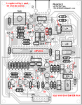
hi, can anyone provide me with pickit 2 schematic and pcb files without SMD components...those r not available locally. thanks
 
yes. the PCB layout is in this forum both smd and non smd :)
 
  • Like
Reactions: azaoth

    azaoth

    Points: 2
    Helpful Answer Positive Rating
they are right here by Nishal
Only issue while soldering check pin-out of transistors and FETs, if needed swap pins.
One loop was missing i shall indicate, you can change it at pcb stage itself by marker pen
the said changes are indicated in the attachment
 

Attachments

  • nishals pickit2 FET TRANSISTOR MRKG.PNG
    nishals pickit2 FET TRANSISTOR MRKG.PNG
    105.8 KB · Views: 194
Last edited:
can some one post a working ckt of pickit 2 lite? i am getting confused with the different schematics uploaded...i just need it to program my pic offline... thanks in advance
 

can some one post a working ckt of pickit 2 lite? i am getting confused with the different schematics uploaded...i just need it to program my pic offline... thanks in advance
Here is the one you were looking for. Cheers and good luck
 

If you are referring to microchip pickit2, perhaps NO.
. however you do calibrate the picit for 3.3V , but, instead you may have to configure external Vdd. i didnt get a chance of programming a 3.3V device, though.
Perhaps the User guide describes the situation
 

Hello.
There is my full PICkit 2. Scheme comes from here: **broken link removed**. I make PCB with normal transistors. Dimension PCB is: 6x10cm.
 

Attachments

  • EAGLE.rar
    80.3 KB · Views: 172

Hello.
There is my full PICkit 2. Scheme comes from here: **broken link removed**. I make PCB with normal transistors. Dimension PCB is: 6x10cm.

this schematic lacks few resistors like 4.7K at the output to ground for clock and data pins. these are needed for some functions as per the pickit2 user manual.
perhaps the designer has skipped them for reasons known to him
 

Hi mvs sarma..

So do you guys have a fully working PicKit 2 through hole version now? Im a newbie, i really need to build this programmer. Can you pls post a working version here?

Thanx
 

Here is one :
 

Attachments

  • PICKIT 2 Clone.rar
    101.9 KB · Views: 173

@ john blue

The schematic you have posted is not the full version as i can see. BTW thanx for your post.

---------- Post added at 10:14 ---------- Previous post was at 10:10 ----------

Do you have the full version (through hole)? if so pls share it. Thanx
 

@ john blue

The schematic you have posted is not the full version as i can see. BTW thanx for your post.

---------- Post added at 10:14 ---------- Previous post was at 10:10 ----------

Do you have the full version (through hole)? if so pls share it. Thanx

Here it is: version from mvssarma
 

Attachments

  • Pickit_version 2_lay.pdf
    626.7 KB · Views: 233
  • Like
Reactions: omega6

    omega6

    Points: 2
    Helpful Answer Positive Rating
@ john blue

Thanx alot for the schematic. BTW is it fully functional? i mean PTG and voltage calibration and other stuff. Sorry for these stupid questions, just need to make sure everything is working before buying the parts and all.

Thanx
 

@ john blue

Once again thanx alot for your help and answers. :smile:
 

Hey Guys..!!

Im unable to find the BS250 and other SMD parts mentioned here. So im using IRFI9Z34G for P-Channel MOSFETs. The original IRLML6402 has RDS(on) = 0.065ohm and the NTD20P06 has RDS(on) = 0.130ohm while the IRFI9Z34G has RDS(on) = 0.14ohm. So will it work in the programmer?

Thanx..

Data Sheet attached below..
 

Attachments

  • irfi9z34g.pdf
    178.4 KB · Views: 107

Hey Guys..!!

Im unable to find the BS250 and other SMD parts mentioned here. So im using IRFI9Z34G for P-Channel MOSFETs. The original IRLML6402 has RDS(on) = 0.065ohm and the NTD20P06 has RDS(on) = 0.130ohm while the IRFI9Z34G has RDS(on) = 0.14ohm. So will it work in the programmer?

Thanx..

Data Sheet attached below..


Can you try? should not be problem
 

At the outset i should thank mahesh holla, of Bangalore, India, who helped me bring this pcb to the ver2 level. Farnell sells IRLML6402 and it is not costly. alternately SI2302 is available in SOT23
compatible
the artwork we tried and used smd as BS250 has higher ON resistance at 10 ohms and it was problematic
we did not want to make the unit bulky by using TO220 devices.
 

Status
Not open for further replies.

Similar threads

Part and Inventory Search

Welcome to EDABoard.com

Sponsor

Back
Top