Continue to Site

Welcome to EDAboard.com

Welcome to our site! EDAboard.com is an international Electronics Discussion Forum focused on EDA software, circuits, schematics, books, theory, papers, asic, pld, 8051, DSP, Network, RF, Analog Design, PCB, Service Manuals... and a whole lot more! To participate you need to register. Registration is free. Click here to register now.

[SOLVED] Pic 16f876a Pure Sinewave inverter

Status
Not open for further replies.
Californiajoe,
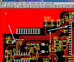
I thank you so much for all your effort,i have been following this sine wave inverter project one by one is now the time for me to see if i can do it,from your pcb what is the dimension in millimeter.
Which of the source code do you use?.
 

Dimension is standard 160 x 100 mm.

Regards
 

Attachments

  • sine_pwm_voltage-regulator_32_int_28.01.2009.rar
    4.9 KB · Views: 572

Thank you very much Californiajoe, i will commence on in,but i will not use the monitor.
 

About pin 2: you can run Inverter without analog signals if you connect resistor of ~ 470 ohm between one of the marked place and GND. Or on the other way, if you meassure voltage on pin 2 of MCU, there should be less than 1,5V.
And remember, this is just for testing. When inverter is completed, you should remove this resistor.

Regards
 

Attachments

  • PIN 2.PNG
    PIN 2.PNG
    30.8 KB · Views: 289

Hello Californiajoe
One question. The inductor of output filter of transformer is 6.8uH? Taner said in this page: https://www.edaboard.com/threads/96053/, he attache the pdf. In this pdf the rated inductance is 1.8 mH to 68 mH.

I believe that is 6.8mH. What do you think??

Regards!!:wink:
 

Yes, you are right. On that pdf induktance is 1,8 - 68mH.
At the momment I don't have output filter, but I plan to do it by myself. I think it's important what load you will supply with inverter. When I'll be at that point, results will be shared with you.

Regards
 
  • Like
Reactions: surat

    surat

    Points: 2
    Helpful Answer Positive Rating
babalola our present output of the inverter and input to the transformer is app. 6-8V, we cant use the same output transformer for battery charger because its an 8:230V transformer and for charger we must have a 220:12v transformer at least, other wise we have to use buck boost converters to regulate power and current rating of charger which itself is a complete project, we can design a transformer for both values (8V and 12V) but still we cant use it for both purposes because for charging output current of 12V side may increase upto 10-20A (typically 7-10A), which furhter arise overheating and over load issues of the transformer so the cooling system must be upgraded for the reason.it is difficult to implement but not impossible, using proper system and high quality transformer we can use it for charging. also please consider transformer loss strictly, less loss, more relaxation for us

Also present code occupy sufficient space in the MCU memory, My recomendations are not to increase load on present MCU for better performance, but we can use it in a simple way i.e using relay logic, first find a high quality transformer haveing 230:8V and 12V tabs (i.e if 230V is input it must have two output tabs at the same time 8V and 12V may be easily available in your local electronics market) then i'll help you how to implement relay logic.

Best Regards

---------- Post added at 11:56 ---------- Previous post was at 11:45 ----------

daniello_85 Output filter Choke is EPCOS 2x6.8uH, 4A

---------- Post added at 12:03 ---------- Previous post was at 11:56 ----------

Californiajoe I have Altium Designer09 installed in my computer which is present version of Protel, I hope it will open your PCB files too, also if you can save it as Protel Advanced file I can edit it in Altium Designer.

Best Regards
 

I don't have option save it as Protel Advanced file. As you can see, this is version from 1994.

Regards
 

Attachments

  • Protel.PNG
    Protel.PNG
    47.2 KB · Views: 162
  • Like
Reactions: kabiru

    kabiru

    Points: 2
    Helpful Answer Positive Rating
it is old version of Altium Designer, in 99 Protel Designer became Altium Designer, pm me source pcb files, i hope it will work with altium designer too

best regards
 

it works Yuhuuuuuuuuuu...........
 

Attachments

  • INV_BRAI Layout.pdf
    131.5 KB · Views: 664

upload output part too.......

Thanks..........................................:)
 

Very nice!
Remember: there are some diferences which were already described.

Regards
 

Attachments

  • INVERT_1.rar
    8 KB · Views: 490

babalola our present output of the inverter and input to the transformer is app. 6-8V, we cant use the same output transformer for battery charger because its an 8:230V transformer and for charger we must have a 220:12v transformer at least, other wise we have to use buck boost converters to regulate power and current rating of charger which itself is a complete project, we can design a transformer for both values (8V and 12V) but still we cant use it for both purposes because for charging output current of 12V side may increase upto 10-20A (typically 7-10A), which furhter arise overheating and over load issues of the transformer so the cooling system must be upgraded for the reason.it is difficult to implement but not impossible, using proper system and high quality transformer we can use it for charging. also please consider transformer loss strictly, less loss, more relaxation for us

Also present code occupy sufficient space in the MCU memory, My recomendations are not to increase load on present MCU for better performance, but we can use it in a simple way i.e using relay logic, first find a high quality transformer haveing 230:8V and 12V tabs (i.e if 230V is input it must have two output tabs at the same time 8V and 12V may be easily available in your local electronics market) then i'll help you how to implement relay logic.

Best Regards

---------- Post added at 11:56 ---------- Previous post was at 11:45 ----------

daniello_85 Output filter Choke is EPCOS 2x6.8uH, 4A

---------- Post added at 12:03 ---------- Previous post was at 11:56 ----------

Californiajoe I have Altium Designer09 installed in my computer which is present version of Protel, I hope it will open your PCB files too, also if you can save it as Protel Advanced file I can edit it in Altium Designer.

Best Regards

jami007, could you explain more preciselly relay logic for chargeing the battery?

Regards
 

hi jami007,
i read in some forum that there is a way to use the same transformer to boost the 6.5v to 12v by turning on the two lower mosfet at the same time to short circuit the transformer, this i learnt will boost the voltage because of the linkage inductance of the tranformer when again the lower fet is diactivated. this system they said is called boost dont know if anybody has detail understanding of this technics.
regards.
babalola
 
  • Like
Reactions: yellow

    yellow

    Points: 2
    Helpful Answer Positive Rating
we can use relay logic to switch transformer between inverter and charging circuit, my proposed idea is to use inverse relay logic, i.e when main supply is on the relay is energized and charging circuit is connected through N.O contacts because relay is energized by main supply whith the help of a small circuit, and when main supply goes off relay de-energize and disconnect transformer and battery from charging circuit and switch and connect the transformer and battery with inverter. in this proposed idea we dont have to write a software for switching we just use main supply line for switching purpose, so it behaves like a UPS, a power relay can switch in micro seconds so fullfill the requirement of switching in less than 2ms of a modern MCU based UPS monitor
 
  • Like
Reactions: yellow

    yellow

    Points: 2
    Helpful Answer Positive Rating
attached circuit is proposed by Taner for converting inverter into UPS with software modifications, it has zero cross detector and switching relays, the missing circuit of pins REL and ZC in the inverter diagram, we can use the same circuit without ZC detector to switch the relays, this is simple relay logic, but we use it in reverse, i.e when main supply is on (AC_in) our relays will be energized and completes the circuit (AC_Out) through N.O (Normally Open) contacts (which are close when relay enrgize) and when main supply goes off relays de energized and complete circuit through N.C (Normally Close) contacts, so by using inverse logic we can switch our output from main line to Inverter output without any software modification, same logic applied for transformer switching (between charging circuit and inverter output) and battery connection switching (between charging circuit and inverter input), to operate the relay from main line we need a small 230-12V transformer, bridge rectifier and 5V rectifier to give input to transistor base(REL) in addition to the Taner's circuit. I hope my idea is clear to every one, any suggestions and remarks will be warmly welcomed.
 

Attachments

  • PIC16_Sine-wave_Inverter_UPS.pdf
    102.6 KB · Views: 783

a relay has operation ratings, e.g 12V, 25A,switching time. So consider requirements strictly, e.g for charging circuit and inverter input a relay of more than 20A will be required. most of the time relays are cheap solution. there are many types of relays so use the best and cheap choice, for our requirements electromagnetic relys are cheap and good solution instead of high price solid state relays.
 
Last edited:

I think, I will use Inverter monitor to control chargeing. I already made analog control of U_BAT, so I need one digitalal input for controling a status of the Inverter and one digital output to control a charger. What do you say?

Regards

---------- Post added at 09:49 ---------- Previous post was at 08:55 ----------

One more question. I would need 12VDC to 5VDC converter (something simpliest as possible). I need separate suply for Inverter monitor becouse of the GLCD.

Any suggestion would be appreciated.

Regards
 

the inverter has two voltage regulators, 10v and 5v, you can use it
 
  • Like
Reactions: yellow

    yellow

    Points: 2
    Helpful Answer Positive Rating
Status
Not open for further replies.

Part and Inventory Search

Welcome to EDABoard.com

Sponsor

Back
Top