Continue to Site

Welcome to EDAboard.com

Welcome to our site! EDAboard.com is an international Electronics Discussion Forum focused on EDA software, circuits, schematics, books, theory, papers, asic, pld, 8051, DSP, Network, RF, Analog Design, PCB, Service Manuals... and a whole lot more! To participate you need to register. Registration is free. Click here to register now.

[SOLVED] Grounded CPWG using momentum

Status
Not open for further replies.

Andres Zarate-de Landa

Newbie level 3
Joined
Nov 20, 2010
Messages
3
Helped
0
Reputation
0
Reaction score
0
Trophy points
1,281
Activity points
1,310
Hello,

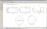
Using Matlab code I developed and AWR Tx-line calculations I got for a 50 Ohms coplanar waveguide line with ground plane
W = 51 mil ==> Line Width
G = 6 mil ==> Gap Width

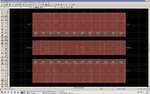
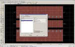
I'm trying to simulate it in ADS momentum, I'm using single ports for the line, and ground reference ports for the ground planes. However I want to know if I have to place vias to ground and if so how to place them in momentum. I'm more used to CST microwave studio and I want to corroborate the simulation data using both programs.

Any help will be much appreciated.
 

Defining a Ground Reference
Ground references enable you to add explicit ground references to a circuit, which may be necessary if no implicit grounds exist in your design.
Implicit ground is the potential at infinity, and it is made available to the circuit through the closest infinite metal layer of the substrate. Implicit grounds are used with internal ports and with single ports that are connected to objects on strip metallization layers.
There are instances where the distance between a port and its implicit ground is too large electrically, or there are no infinite metal layers defined in the substrate. In these cases, you need to add explicit ground references to ensure accurate simulation results. For more information on using ground references, refer to Simulating with Internal Ports and Ground References.

You can apply ground references to the surfaces of object. The object must be on strip metallization layers.

Note
Multiple ground reference ports can be associated with the same port. To be associated with a single port, the ground reference port should be a port attached to an edge of an object in the same reference plane as the single port.

To add a ground reference:

Choose Momentum > Ports > Editor.
Select the port that you want to assign as the ground reference.
In the Port Editor dialog box, under Port Type, select Ground Reference .
Under Associate with port number , enter the number of the single or internal port that you want to associate with this ground reference. Make sure that the distance between the port and ground reference is electrically small.
Click Apply .

No need via for CPW.
 
No need via for CPW.

I understand that the question refers to a CPW with additional ground plane below. In this case, you should model what you build in the hardware. If the hardware contains vias connecting the CPW ground strips with the ground below, then these should also be included in the simulation model.
 

Thank you all for your answers.

I know that for CPW there's no need for vias and just grounded ports referenced to single ports will do the job. However, I'm working with grounded CPW, so I thought about adding vias, but I don't know if I did it correctly. I defined the substrate as via in the hole layer, then I set VIAGND from the library and defined Cond1Layer = "cond" , HoleLayer = "Hole" I'm attaching a couple of images. I hope what I did can give me more accurate results.

Thank you so much
 

Attachments

  • grounded_cpw.jpg
    grounded_cpw.jpg
    664.8 KB · Views: 248
  • substrate.jpg
    substrate.jpg
    553.2 KB · Views: 200

Thank you all for your answers.

I know that for CPW there's no need for vias and just grounded ports referenced to single ports will do the job. However, I'm working with grounded CPW, so I thought about adding vias, but I don't know if I did it correctly. I defined the substrate as via in the hole layer, then I set VIAGND from the library and defined Cond1Layer = "cond" , HoleLayer = "Hole" I'm attaching a couple of images. I hope what I did can give me more accurate results.

Thank you so much
Why you have attached ports to the ground plane ?? They are normally connected to ground through VIAs.The layout should normally have 2-Ports.
P1 and P2 are sufficient.
 
I read that for coplanar structures there's supposed to be ground reference planes. I simulated using both configurations, attached I'm showing results for grounded coplanar with ground reference ports and vias (red), with vias and just single ports (blue), and with no vias and ground reference ports (green). I can see that green results are not accurate but I don't know which of the other two are correct. Big Boss are you 100% sure there's no need for ground reference ports? I'm getting confused right now I've read so much info I don't know which one is correct.

Thank you so much for your help.
 

Attachments

  • Results.jpg
    Results.jpg
    204.5 KB · Views: 173

Hi, Andres, I simulated one grounded CPW, and you can test it. There is no difference between 6 ports (4 grounded) and 2 ports.
 

Attachments

  • Mom_test_prj3_prj.zip
    2.9 MB · Views: 160
Status
Not open for further replies.

Part and Inventory Search

Welcome to EDABoard.com

Sponsor

Back
Top