Continue to Site

Welcome to EDAboard.com

Welcome to our site! EDAboard.com is an international Electronics Discussion Forum focused on EDA software, circuits, schematics, books, theory, papers, asic, pld, 8051, DSP, Network, RF, Analog Design, PCB, Service Manuals... and a whole lot more! To participate you need to register. Registration is free. Click here to register now.

[SOLVED] 12Vdc to 220Vac 3000W Inverter Full Schematics And Pcb

Status
Not open for further replies.
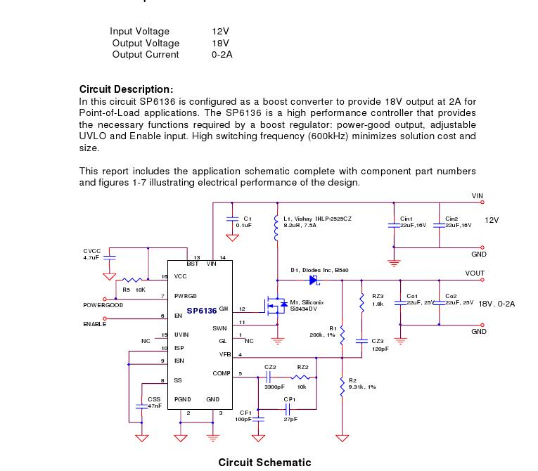
Thanks Gazali Zuberi for the info on this circuit
I want to make a 500W inverter from this circuit and omit the no load and overload detectors to make it simple
will it be OK?
Thanks

Hi Andy, sorry for the late reply. Yes a 500W inverter based on this circuit would be a more feasible option and you can omit the load detection circuit. 3000W is quite impractical with a 12V battery, whereas loads in the range of 500~1500W are more practical and easily achievable.

Good luck with your endeavours,

BR, Ghazali

PS: details on omiting of Load Detection circuit are included in the material.
 
may i get the schematic n pcb for 12vdc to 220vac inverter too.. thanks..

yar i just want 12volt dc to 18watt inverter. plz any body can share its schematic only.
also i want to know what is this ferrite core transformer and how its differnt from other transformer?
 

A transformer with a ferrite core is used only at high frequencies and a normal transformer with a laminated iron core works only at low frequencies.
 
what do mean by ''12volt DC to 18W inverter''
 

what do mean by ''12volt DC to 18W inverter''
Guess he is refering to 12 volt to 18 volts Boost converter which can be used to charge a laptop on the move. But this querry / topic doesn't relate to this particular thread.

i want to know what is this ferrite core transformer and how its differnt from other transformer?
While regular transformers use metal plates as Core material which has a limitation in frequency and its efficiency, the ferrite transformer uses fine magnetic material mixed with ceramic to create a Ferrire core which is highly suitable for high frequency designs such as SMPS.
Cheers
 

yar i just want 12volt dc to 18watt inverter. plz any body can share its schematic only.
also i want to know what is this ferrite core transformer and how its differnt from other transformer?

12 volt to 18 volts Boost converter !
 
Hi Audioguru, as I told you in the past, there is countries in the world that need inverters, Canada is not the world, there is the whole of Africa where infrastructure is non existing, high tension lines is destroyed, thanks to the white man that is driven out of the continent and with the high prize of copper it did not take long for the transmission lines to disappear. Even South Africa, that was a first world country before the nineties with one of the strongest economies in the world is under supplied at the moment. But there is still a need for mains power and an inverter is the only way, you are right to say you can't use a 12V car battery to generate 3KW, but 3KW is the least power that is needed for a household therefor you need at least 4 high power batteries in series and to charge the batteries,there is many ways to do it. There is wind chargers, solar panels, waterwheels and sterling engines to only mention some.
To come to a point, why don't you? as I asked you in the past help the guys with a design, I do have one that can do up to 10KW but it is my patent and to share it is to shoot myself in the foot and you, do have the expertise to help.

---------- Post added at 23:20 ---------- Previous post was at 23:10 ----------

PS. The Japscrap is not an answer.
 

Hi Audioguru, ..... there is the whole of Africa where infrastructure is non existing
I know. Africans come to Canada and cannot believe that we have continuous electricity, natural gas heating, air conditioning, cable TV and running drinking water in every home.
Two completely different worlds.
 

3000W Inverter Full Schematics And Pcb

A-O-A
some confusion of the drawing and PCB for what use it ???? :!:
:!::!::!::!:
attache the PCB lay out and drawing image ..


drawing PCB
 

Attachments

  • pcb 2.GIF
    pcb 2.GIF
    77.5 KB · Views: 264
  • 1 drawing.GIF
    1 drawing.GIF
    56 KB · Views: 406

Re: 3000W Inverter Full Schematics And Pcb

A-O-A
some confusion of the drawing and PCB for what use it ????

@snowday
whats the confusion, may i ask?
 

what is a,b,c,d,e,f g,+,-. point connection please complete inform me
 

AandB=Oscilator output,C=Overload sensing,D=Voltage control,E=Load detection to trigger stable oscilation,F=Load indicator.If you read the text you will understand it more.

---------- Post added at 16:29 ---------- Previous post was at 16:24 ----------

But do not try building 3kv with 12v otherwise your battery will bust in few minute or burning your cables.
 
Hi snowday!
actually i have not yet made this project
3000VA is not practically viable with a 12V battery because of the huge current required
a 500VA or 600VA project without "load detection" and "overload protection" circuitry becomes more simple to make
A LM7812 regulator IC is used to supply regulated DC voltage to the circuit when we all know that after running for sometime the battery voltage will go down to about 10 volts.
Moreover a LM7812 IC must have at least 15 volts at input to function properly therefore it will be better to use a LM7808 regulator IC if we dont use IC10 charge pump circuit
If we look at the circuit diagram and the pcb components layout
then point A and should be interchanged with point B to match with the circuit diagram
Thanks to "kabiru" for the explanation
 
Last edited:

@Ghazali Zuberi
since you have made it, can you please tell me what voltage you are getting at the input of LM7812 regulator IC after about one hour use, assuming you have installed the IC10 TL081 charge pump circuit?Because i am thinking of not useing the IC10 charge pump circuit and instead use a LM7808 regulator IC
Thanks!
regards
 

And where is Doctor_E who started this thread?
why is he not participating in the discussion?
EDIT: sorry, did not notice that the original post was on 15th March 2006 , more than 5 years ago!!
 
Last edited:

Andy G and kabiru thanks for reply.
any body made it please complete information post.
 
Last edited:

sir Ghazali Zuberi can i have i copy of your design with a 850Va output Transformer,,,,,,
can u help how to modify the circuit to make the output with only 1000w power,,,,,

---------- Post added at 15:12 ---------- Previous post was at 15:06 ----------

Assalam o Alaikum Guys,

This is an old circuit designed by legendary German engineer Mr. Wolf-Guenter Gfrorer in 1998. Now it is only avaiable at inverter. With full description of the circuit, transformer computations, PCB and complete testing procedures.

I built this circuit in 2001, with a 850VA output Transformer. It's a good robust design. Mine still works fine.

PS:- All the parts are commonly, easily and cheaply available in Pakistan, specially Karachi. If somebody require some particular components in Karachi, please feel free to contact me for supply store addresses.

Best Regards,

Ghazali Zuberi

Added after 20 minutes:

for your convenience I am attaching a copy of the complete web page.

here is the file in rar format, with web page in mht format.

sir Ghazali Zuberi can i have i copy of your design with a 850Va output Transformer,,,,,,
can u help how to modify the circuit to make the output with only 1000w power,,,,,
 

Status
Not open for further replies.

Part and Inventory Search

Welcome to EDABoard.com

Sponsor

Back
Top