Continue to Site

Welcome to EDAboard.com

Welcome to our site! EDAboard.com is an international Electronics Discussion Forum focused on EDA software, circuits, schematics, books, theory, papers, asic, pld, 8051, DSP, Network, RF, Analog Design, PCB, Service Manuals... and a whole lot more! To participate you need to register. Registration is free. Click here to register now.

Circuit for S21 Measurement of Transimpedance Amplifier

Status
Not open for further replies.

mycw

Junior Member level 3
Joined
Sep 29, 2010
Messages
30
Helped
2
Reputation
4
Reaction score
1
Trophy points
1,288
Activity points
1,500
Hello everyone,

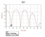
I'm trying to measure S21 of TIA in ADS, where s2p file is given, but I found from S21 response some unexpected periodical attenuations and I couldn't figure out the reason. Does anyone have a clue?

Testing circuit and S21 response are attached. Except the terminal for s-parameter measurement was added by me, remaining lump element values were recommended values from TIA manufacturer.

Thanks a lot!

Mario Young
s21.jpgcircuit.jpg
 

Why not try to remove all the L/C/Probe, just remain the two term?
 
  • Like
Reactions: mycw

    mycw

    Points: 2
    Helpful Answer Positive Rating
Has your TIA been characterized beyond 5GHz ?? If it's not been done, ADS will extrapolate the s-parameters which are probably not correct.
 
  • Like
Reactions: mycw

    mycw

    Points: 2
    Helpful Answer Positive Rating
Aren't transimpedance amps current sources at their outputs, like for driving a low impedance laser diode? If so, then Measuring 2 port s parameters is going to be folly.
 

Thanks for all your replies.

To Tony: I tried to removed all lumped components leaving the two terminals but I found same result, well, almost the same, just a little bit change on the magnitude.

To BigBoss: yes, this TIA is characterized from 0 to 50GHz, this is confirmed from the s2p file.

To biff44: I think you mean current in and voltage out. Some manufacturers provide S21 graph in their product's datasheet, yeah, it sounds weird, initially I thought that s-parameters are only related to incident & reflected voltages, maybe someone could explain this part :)

By the way, I went through the s2p file again and I realized that, this attenuation effect seems to be caused by the file itself, because on those attenuated frequencies, like 8GHz, 21GHz and 33GHz, the real parts are small values. Now waiting for the manufacturer's reply.
 

Yep, you are right. These are from being driven by a current source, like a PIN photodiode, and outputing a voltage.

So, by design they want the input impedance to be zero, right? So, my basic comment is still valid, what use is an S parameter? I would thing some other parameter, like z or h parameter, would be more valid.
 

I am surprised to see those low input/output impedances that you are using for testing the TIA chip.
From my knowledge TIA chipsets have much higher input/output impedances (hundreds of ohms up to few kilo-ohms, depending by the technology process used).
 

Initially, I thought that impedance matching circuit is needed, but later on, I found from the textbook stating that TIA implemented with op amp doesn't possess high input impedance, in fact, it can be low as 50 ohm only.
There is a brief explanation in Wikipedia: search for "current-to-voltage converter", then find for "input impedance".
 

Status
Not open for further replies.

Part and Inventory Search

Welcome to EDABoard.com

Sponsor

Back
Top