Continue to Site

Welcome to EDAboard.com

Welcome to our site! EDAboard.com is an international Electronics Discussion Forum focused on EDA software, circuits, schematics, books, theory, papers, asic, pld, 8051, DSP, Network, RF, Analog Design, PCB, Service Manuals... and a whole lot more! To participate you need to register. Registration is free. Click here to register now.

How to simulate a TIA (transimpedance measurement)

Status
Not open for further replies.

keisini5577

Newbie level 6
Joined
Oct 11, 2010
Messages
12
Helped
0
Reputation
0
Reaction score
0
Trophy points
1,281
Activity points
1,360
hi ,

here I have a question about how to simulate a TIA. I'm working on a TIA with spectre. I want to measure its gain. How shall I establish the test bench?

I have two differential Isin with proper bias current and run the AC simulation. Then I use the direct plot "gain & phase", first click on the output voltage and then on the input voltage. Is what I get only the voltage gain of the amplifier?
How can I get the transimpedance gain?

Thank you in advance!
 

If you use a current source as the input to a transimpedance amplifier then the voltage out from an AC anaylsis is the transimpedance, even if that might be displayed in dB. If it is 60dB then it really means 1k ohm.

Keith.
 
If you use a current source as the input to a transimpedance amplifier then the voltage out from an AC anaylsis is the transimpedance, even if that might be displayed in dB. If it is 60dB then it really means 1k ohm.

Keith.


thanks, but I don't quite understand... do you mean the voltage output in "V"? so I only need to plot the output voltage?
 

If the output you plot is "Volts" then it will really mean "Volts per Amp" if you used a current source input. Volts/amp = resistance or "transimpedance".

What output are you getting and what is your circuit?

Keith.
 

If the output you plot is "Volts" then it will really mean "Volts per Amp" if you used a current source input. Volts/amp = resistance or "transimpedance".

What output are you getting and what is your circuit?

Keith.

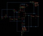
My ciruit looks as following image:

TIA.jpg

the differential cuurent input setting is : AC magnitud=1A AC phase=0/180 AC amplitude=1p A DC current= 17u A

Another problem is that I don't quite understand the meaning of AC Magnitude when using it in the simulation for differential amplifier.
 
Last edited:

If this is a photodiode amplifier I am puzzled why you are using a differential one. You only have a single ended input so your simulation should only have one signal source.

You should use AC magnitude of 1, not 1p. It will work with 1p but it serves no useful purpose in an AC simulation other than to scale the numbers.

Attached is the sort of result I would expect.

Keith.
 

Attachments

  • AD8655 transimpedance.pdf
    7.9 KB · Views: 269
  • Like
Reactions: keisini5577

    keisini5577

    Points: 2
    Helpful Answer Positive Rating
    V

    Points: 2
    Helpful Answer Positive Rating
I'v make a mistake... but I did use AC magnitude of 1, 1p is the amplitude. When I want to get the gain, shall I use the calculator to plot the output voltage to input current("Volts/amp ")?
 

Simply plot the output voltage. The units will actually be "resistance" even if the plot shows the Y axis as VOLTS.

Keith.
 

Status
Not open for further replies.

Part and Inventory Search

Welcome to EDABoard.com

Sponsor

Back
Top