moonnightingale
Full Member level 6
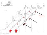
problemof adder
I know how to make it with and gates and 1 bit full adder but how to use 4 bit adders
I know how to make it with and gates and 1 bit full adder but how to use 4 bit adders
Last edited: