Continue to Site

Welcome to EDAboard.com

Welcome to our site! EDAboard.com is an international Electronics Discussion Forum focused on EDA software, circuits, schematics, books, theory, papers, asic, pld, 8051, DSP, Network, RF, Analog Design, PCB, Service Manuals... and a whole lot more! To participate you need to register. Registration is free. Click here to register now.

startup ciruit ...how does the node 1 go to vdd...?Thankyou...

Status
Not open for further replies.

bhanu.somisetty

Newbie level 6
Joined
Oct 17, 2006
Messages
12
Helped
0
Reputation
0
Reaction score
0
Trophy points
1,281
Activity points
1,355
Hi All...

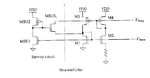
In the attachment,the startup circuit is used to avoid a condition "where the gate voltages of transistor M1,M2 become zero and M3,M4 become VDD and the circuit doesnt work".
Can anyone explain,why the gate voltages of M1,M2 go to zero and M3,M4 go to VDD?

Thanks a lot....
 

Attachments

  • startup_betamultipler.JPG
    startup_betamultipler.JPG
    12.8 KB · Views: 181

If you ignore the startup circuit the circuit is 'bistable'. It has two stable states - working as designed and with all transistors 'off'. When you power up the circuit the gates of M1 and M2 could be VSS and the gates of M3 and M4 could be VDD and the circuit would happily stay like that. The startup circuit stops that from happening without affecting the normal operation.

Keith
 

    V

    Points: 2
    Helpful Answer Positive Rating
Hi

Thanks for the explanation.Would you pls let me "why the M3 and M4 gate voltage goes to VDD?"
 

This device is diode connected. At startup with zero current flowing the vgs will stay below vth (it does not need to be at vdd) when the power is applied slowly.
 
The PMOS transistors have the bulk connected to VDD. The gate capacitance will tend to keep the transistors turned off although the drain capacitance and leakage of the NMOS will try to pull the PMOS gates low. The end result is unpredictable without a startup circuit.

Keith
 
if no start up circuit, when the circuit is initial, M1/M2 and M3/M4 are depth linear, So gate voltage of M1 and M2 is about gnd, gate voltage of M3 and M4 is vdd,
 

Status
Not open for further replies.

Similar threads

Part and Inventory Search

Welcome to EDABoard.com

Sponsor

Back
Top