Continue to Site

Welcome to EDAboard.com

Welcome to our site! EDAboard.com is an international Electronics Discussion Forum focused on EDA software, circuits, schematics, books, theory, papers, asic, pld, 8051, DSP, Network, RF, Analog Design, PCB, Service Manuals... and a whole lot more! To participate you need to register. Registration is free. Click here to register now.

measuring pulse frequency using timer0

Status
Not open for further replies.
your code wouldn't work because you didn't provide a way for it to work.
Why it is so? I think i have defined every thing,I am doing nothing in the main loop,whenever an external interrupt comes it saves the last timer value and reset the timer and then display the value.

The code you have given me is absolutely right but code always stuck in a while loop for calculating/seenig the state of the pulse.

If i use a timer value and reset it when ext int come,i think this will be more efficient way.This is my opinion,you are experienced people you can tell the better way for solving this.
I have to preform other tasks also like count the number of pulses coming from ext interrupts and based on these pulses perform other calculations and also calculate the frequency.
 

if you follow your code, what results will it provide? just walk yourself through it one statement at a time and you will see what happens.
 

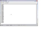
millwood i am running my code and currently i am giving pulses of 10Hz,the attached image shows the timer value at 10Hz,
According to timer settings:
presclaer value =8
timer0 = 16-bit mode
in this configuration the timer will increment every 1.6us.
when the ext interrupt comes it save the value of timer0 let say from the figure 60875.
now multiply 60875*1.6uS = 0.0974 sec
then convert it into frequency f=1/t = 1/0.0974 = 10.26Hz which is very close to 10 Hz.

If i increase the frequeny the values which are displaying on the hyperterminal matches the frequency applied, but on higher frequency the values are incorrect.
This problem has to be solved.

Hope i am correct
 

Attachments

  • hyperterminal.JPG
    hyperterminal.JPG
    54.7 KB · Views: 80

I meant for you walk yourself through the execution of the code (as if you were the mcu) and then you would know what went wrong.

external interrupt is not particularly fast and anything more than a few khz wouldn't work, even if your code is efficient (and yours isn't).

---------- Post added at 11:41 AM ---------- Previous post was at 11:38 AM ----------

to give you a better sense, here is a similar piece of code that measures the pulse width of an incoming pulse train, up to us.

again, it was written for a PIC but then ported to C51.

Code:
#include <regx51.h>
#include "gpio.h"

//__CONFIG(MCLRDIS & BORDIS & WDTDIS & PWRTEN & INTIO);

#define IN_PORT				P3
#define IN_DDR				P3
#define IN_GATE				(1<<2)		//pulse gate on int0=p3.2

#define OUT_PORT			P2
#define OUT_DDR				P2
#define OUT_PINs			0xff		//all pins on p2 are output

void mcu_init(void) {					//initiate the mcu
	//ANSEL=0x00;							//all pins digital
	//CMCON=0x07;							//analog comparators off
	IO_IN(IN_DDR, IN_GATE);				//in_gate as input
	IO_OUT(OUT_DDR, OUT_PINs);			//out_pins as output
}

void tmr0_init(void) {					//initiate the tmr1
	//TMR1GE=1;							//enable tmr1 gate control - tmr1 starts counting if t1g is low
	//T1CKPS1=0, T1CKPS1=0;				//tmr1 prescaler 1:1
	//TMR1CS=0;							//tmr1 source is internal clock
	TMOD &=0xf0;						//reset tmod0..3
	TMOD |=0x09;						//tmr0 =gated timer, and in mode 1 (16-bit timer)
	//TMR1ON=0;							//tmr0 off
	TR0=0;
}


void
main(void)
{
	unsigned short count=0;

	mcu_init();							//initiate the mcu
	tmr0_init();						//initiate the tmr1
	
	while (1){
		//TODO Auto-generated main function
		while (IO_GET(IN_PORT, IN_GATE));	//wait for in_gate to go low
		//now in_gate is low
		TH0=0, TL0=0;					//reset tmr0 counters
		//TMR1ON=1;						//turn on tmr1
		TR0=1;
		while (!IO_GET(IN_PORT, IN_GATE));	//wait for IN_gate to go high
		//in_gate is high -> counting starts high
		while (IO_GET(IN_PORT, IN_GATE));	//wait for in_gate to go low
		//TMR1ON=0;						//turn off tmr1
		TR0=0;
		count=(TH0<<8) | TL0;		//count contains tmr1h:tmr1l
		IO_CLR(OUT_PORT, OUT_PINs);	//clear output pins
		IO_SET(OUT_PORT, count);	//output
	}
}
 

Attachments

  • C51 TMR0 Gated.PNG
    C51 TMR0 Gated.PNG
    27.6 KB · Views: 89

in this example, the code measures the pulse width, in us, when the incoming pulse train is high.

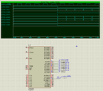
it utilizes the gated tmr0 on a C51. in the particular simulation, we applied a 10Khz signal to the gate (INT0 pin, on p3.2). so the pulse width should be 50us. The output is shown on P2, as 0x32 = 50, as the mcu is running on 1us per timer tick.

a gated timer the most accurate approach as it is entirely hardware driven.
 

measuring the pulse width is really not the best way to measure frequency. a better approach is to count the number of pulses during a given period of time. that approach utilizes a counter rather than timer.

assuming you want to stay with your approach, you need to make sure that your code measures pulse width as accurately as possible. here is a couple of issues you may want to address with your code:

1) your code does not read the prescaler: with a divide-by-8 prescaler, you are missing potentially 8 timer ticks.
2) your code isn't compensating for the overhead associated with the ext int isr.

you may also consider how you are going to deal with a wide range of pulse width, and how to prevent the isrs to be fired up when you are transmitting on lower speed uart.

---------- Post added at 02:32 PM ---------- Previous post was at 02:03 PM ----------

I put this together and hopefully it will send you on the right path.

it goes along the same line as yours but simpler, as it utilizes tmr1.

Code:
//not a very efficient way to measure pulse width on 12F675

#include <htc.h>
#include "gpio.h"

__CONFIG(MCLRDIS & BORDIS & WDTDIS & PWRTEN & INTIO);

#define EXT_INT_PORT			GPIO
#define EXT_INT_DDR				TRISIO
#define EXT_INT					(1<<2)		//gpio2 is external interrupt pin

#define TMR1_ERROR				0			//tmr1 error term

unsigned short pulse_width;		//pulse width counter

void mcu_init(void) {
	ANSEL=0x00;					//all pins gpio
	CMCON=0x07;					//analog comparators off
}

void tmr1_init(void) {			//initialize tmr1 as timer
	TMR1GE=0;					//no gate control
	T1CKPS1=0, T1CKPS0=0;		//prescaler 1:1
	TMR1CS=0;					//tmr1 source is internal clock
	TMR1ON=1;					//tmr1 off
}

void ext_int_init(void) {		//initialize external interrupt
	IO_IN(EXT_INT_DDR, EXT_INT);	//external interrupt pin as input
	INTEDG=1;					//external interrupt on rising edge
	INTE=1;						//enable ext_int
	GIE=1;						//enable interrupt
}
	
void interrupt isr(void) {		//interrupt service routine
	if (INTE & INTF) {			//a valid external interrupt has taken place
		//TMR1ON=0;				//stop tmr1
		INTF=0;					//reset external interrupt flag
		pulse_width=(TMR1H << 8) | TMR1L;	//read tmr1
		//pulse_width+=TMR1_ERROR;	//correct the error term
		TMR1H=0, TMR1L=0;		//reset tmr1
		//TMR1ON=1;				//start tmr1
		//return;
	}
}
		
	
void
main(void)
{
	mcu_init();					//initialize the mcu
	tmr1_init();				//initialize tmr1
	ext_int_init();				//initialize external interrupt
	
	while (1){
		//TODO Auto-generated main function
	}
}

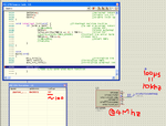
you should pay particular attention to how the isr() works. the error term is 3 timer ticks (=3us) when measuring a 10Khz pulse train. and the code provided a way to correct that as well.
 

Attachments

  • 12F675 Pulse Width Measurement.PNG
    12F675 Pulse Width Measurement.PNG
    39.3 KB · Views: 77

the limitation with the use of the external interrupt pin is that you may have a limited number of such pins. on the other hand, IOC pins are generally plentiful and you can easily modify the code above to measure pulse width with the incoming pulse train connected to any of the IOC (usually on portb) pins.
 

here is the same code, using IOC on GPIO3 to measure the pulse width.

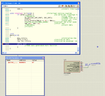
Because of the use of IOC, it is measuring half of the period of the pulse train. for 10Khz pulses, half the period is 50us -> measured at 47us, without error correction.

Code:
//not a very efficient way to measure pulse width on 12F675
//utilizes IOC pins (gpio0..5)

#include <htc.h>
#include "gpio.h"

__CONFIG(MCLRDIS & BORDIS & WDTDIS & PWRTEN & INTIO);

#define IOC_INT_PORT			GPIO
#define IOC_INT_DDR				TRISIO
#define IOC_INT					(1<<3)		//gpio3 is the ioc pin

#define TMR1_ERROR				0			//tmr1 error term

unsigned short pulse_width;		//pulse width counter

void mcu_init(void) {
	ANSEL=0x00;					//all pins gpio
	CMCON=0x07;					//analog comparators off
}

void tmr1_init(void) {			//initialize tmr1 as timer
	TMR1GE=0;					//no gate control
	T1CKPS1=0, T1CKPS0=0;		//prescaler 1:1
	TMR1CS=0;					//tmr1 source is internal clock
	TMR1ON=1;					//tmr1 off
}

void ioc_int_init(void) {		//initialize external interrupt
	IO_IN(IOC_INT_DDR, IOC_INT);	//external interrupt pin as input
	IOCB |= IOC_INT;				//enable ioc on ioc_int pin
	GPIE=1;						//enable interrupt on change
	GIE=1;						//enable interrupt
}
	
void interrupt isr(void) {		//interrupt service routine
	if (GPIE & GPIF) {			//a valid IOC interrupt has taken place
		//TMR1ON=0;				//stop tmr1
		IO_GET(IOC_INT_PORT, IOC_INT);		//dummy read on ioc_int
		GPIF=0;					//reset ioc interrupt flag
		pulse_width=(TMR1H << 8) | TMR1L;	//read tmr1
		//pulse_width+=TMR1_ERROR;	//correct the error term
		TMR1H=0, TMR1L=0;		//reset tmr1
		//TMR1ON=1;				//start tmr1
		//return;
	}
}
		
	
void
main(void)
{
	mcu_init();					//initialize the mcu
	tmr1_init();				//initialize tmr1
	ioc_int_init();				//initialize external interrupt
	
	while (1){
		//TODO Auto-generated main function
	}
}
 

Attachments

  • 12F675 Pulse Width Measurement IOC.PNG
    12F675 Pulse Width Measurement IOC.PNG
    38.2 KB · Views: 79

the above code has one limitation: it cannot measure accurately pulse width longer than what a 16-bit timer can handle - it doesn't detect tmr1h/tmr1l overflows.

that can be addressed easily with software:

Code:
//not a very efficient way to measure pulse width on 12F675
//utilizes IOC pins (gpio0..5)

#include <htc.h>
#include "gpio.h"

__CONFIG(MCLRDIS & BORDIS & WDTDIS & PWRTEN & INTIO);

#define IOC_INT_PORT			GPIO
#define IOC_INT_DDR				TRISIO
#define IOC_INT					(1<<3)		//gpio3 is the ioc pin

#define TMR1_ERROR				0			//tmr1 error term

unsigned short pulse_width;		//pulse width counter
unsigned short tmr1_overflow_counter;	//how many times tmr1 has overflown

void mcu_init(void) {
	ANSEL=0x00;					//all pins gpio
	CMCON=0x07;					//analog comparators off
}

void tmr1_init(void) {			//initialize tmr1 as timer
	TMR1IF=0;					//reset tmr1 flag
	TMR1GE=0;					//no gate control
	T1CKPS1=0, T1CKPS0=0;		//prescaler 1:1
	TMR1CS=0;					//tmr1 source is internal clock
	TMR1ON=1;					//tmr1 off
}

void ioc_int_init(void) {		//initialize external interrupt
	IO_IN(IOC_INT_DDR, IOC_INT);	//external interrupt pin as input
	IOCB |= IOC_INT;				//enable ioc on ioc_int pin
	GPIE=1;						//enable interrupt on change
	GIE=1;						//enable interrupt
}
	
void interrupt isr(void) {		//interrupt service routine
	if (GPIE & GPIF) {			//a valid IOC interrupt has taken place
		//TMR1ON=0;				//stop tmr1
		IO_GET(IOC_INT_PORT, IOC_INT);		//dummy read on ioc_int
		GPIF=0;					//reset ioc interrupt flag
		pulse_width=(TMR1H << 8) | TMR1L;	//read tmr1
		//pulse_width+=TMR1_ERROR;	//correct the error term
		TMR1H=0, TMR1L=0;		//reset tmr1
		//TMR1ON=1;				//start tmr1
		TMR1IF=0;				//reset tmr1 flag
		tmr1_overflow_counter=0;	//reset tmr1 overflown counter
		//return;
	}
}
		
	
void
main(void)
{
	mcu_init();					//initialize the mcu
	tmr1_init();				//initialize tmr1
	ioc_int_init();				//initialize external interrupt
	
	while (1){
		//TODO Auto-generated main function
		if (TMR1IF) {				//tmr1 has overflown
			TMR1IF=0;				//reset tmr1
			tmr1_overflow_counter++;	//increment tmr1  overflown counter
		}
	}
}

tmr1_overflow_counter tracks how many times tmr1 has overflown. so tmr1_overflow_counter is essentially the bits beyond the 16-bit tmr (pulse_width). since we used a "unsigned short" type for tmr1_overflow_counter, we essentially have a 32-bit timer here, capable of measuring 4bn us, or ~4000 seconds.

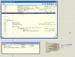
in the attached picture, we are measuring a 1Hz pulse train. pulse_width is 41245 (us), and tmr1_overflow_counter is 7, indicating that the tmr1 has overflown 7 times. so the total time measurement is (7<<16) | 41245=(7*65536) + 41245=499997 (us) = 499.997ms, vs. the real answer of 500ms for the 1Hz pulse train.
 

Attachments

  • 12F675 Pulse Width Measurement IOC 2.PNG
    12F675 Pulse Width Measurement IOC 2.PNG
    36 KB · Views: 78
Millwood thanks for your support,you have given alot of options, i am getting confused day by day.I am looking at your code hope i will understand it.
Can you tell me what parameters are missing in my Code so i add up those parameters.
 

Status
Not open for further replies.

Similar threads

Part and Inventory Search

Welcome to EDABoard.com

Sponsor

Back
Top