Continue to Site

Welcome to EDAboard.com

Welcome to our site! EDAboard.com is an international Electronics Discussion Forum focused on EDA software, circuits, schematics, books, theory, papers, asic, pld, 8051, DSP, Network, RF, Analog Design, PCB, Service Manuals... and a whole lot more! To participate you need to register. Registration is free. Click here to register now.

How to make a PCI Card at ALtium?

Status
Not open for further replies.

Sink0

Full Member level 6
Joined
Nov 25, 2009
Messages
390
Helped
37
Reputation
74
Reaction score
30
Trophy points
1,308
Location
Sao Paulo, Brazil
Activity points
4,186
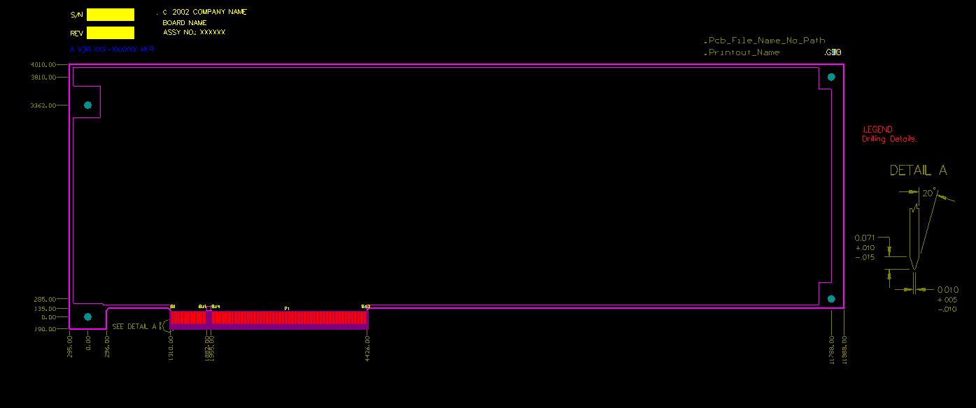
Hi, i am kind a beginner to Altium. I am used to Eagle. I need to make a Standard 32BIT PCI Card. I got the PCI layout with the PCB wizard but i got a problem. I dont know how to show the PCI card connector (that is already placed at the PCB) at the schematic. Any one can help me with that?

Thank you!
 

I ran through the wizard and it appears to work pretty good. When I first completed wizard I did have a blank screen but after refreshing all appeard ok.


eda-
 

Yea .. i see that too. i have the board file with the conector.. but i need to see that conector at a Schematic file so i can make the conections i need... any idea ho to make that?
 

Use schematic templates.
You can even use pcb templates.

Here is one way you can set this up:

1. create new project
2. open schematic template you would like to use. Save it to new project location
3. open pcb template you would like to use. Save it to new project location
4. add both schematic and pcb to new project.

This should get you started.

done


eda
 
  • Like
Reactions: ristabr

    Sink0

    Points: 2
    Helpful Answer Positive Rating

    ristabr

    Points: 2
    Helpful Answer Positive Rating
Hi, I'm trying to do a non-template PCI card and I would like to know how is the process to create a specific PCI card connector footprint linked to schematic in the Altium Designer.

Thank you!
 

simply open the specific PcbDoc template and then use the command >> Design >> Make PCB Library. That will give you the footprint.
Now do the same for the schematics.
 

Status
Not open for further replies.

Part and Inventory Search

Welcome to EDABoard.com

Sponsor

Back
Top