Continue to Site

Welcome to EDAboard.com

Welcome to our site! EDAboard.com is an international Electronics Discussion Forum focused on EDA software, circuits, schematics, books, theory, papers, asic, pld, 8051, DSP, Network, RF, Analog Design, PCB, Service Manuals... and a whole lot more! To participate you need to register. Registration is free. Click here to register now.

adjustable constant current from LM2576adj

Status
Not open for further replies.

CMOS

Advanced Member level 3
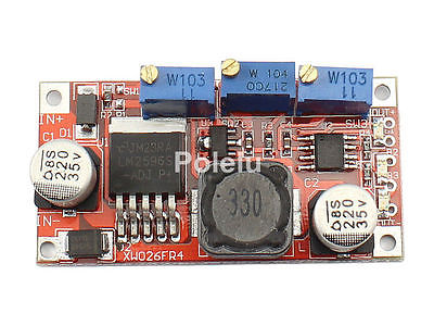
Joined
Jan 6, 2004
Messages
862
Helped
94
Reputation
186
Reaction score
50
Trophy points
1,308
Location
USA
Activity points
5,673
lm2576

I want to construct a 0-30V/0-3A variable power supply using LM2576-ADJ switching regulator. I found a way of current control of this regulator at EDN. I just need to use a potentiometer instead of R6 to change the current. Posted here is the schematic of it.

Now the question is how can I also incorporate voltage control into the same circuit?
 

Attachments

  • lm2576-ps_1913.gif
    lm2576-ps_1913.gif
    18 KB · Views: 1,141

lm2576 schematic

Install the normal feedback resistors and make the top one adjustable. That will allow you to adjust the voltage down to about 1.2V.
Connect the output of the second opamp to the FB pin through a diode, not directly. The cathode should be to the FB pin.
 

lm2576 circuit

Is this what you mean?

Also is it possible to make output voltage to 0V?
 

lm2576 power supply

Yes, that is exactly what I meant.

But I forgot to mention something else: the second opamp should work as a comparator, to the bottom of R6 should be connected to an adjustable voltage, which will allow you to vary the current limit. Also, you may need to play with the value of R7.

But now I think you understand how the circuit will operate: as long as the current is low enough, the output of IC2A will be lower than the "current reference" (the adjustable voltage at the bottom of R6). So the output of IC2B should be low and the regulator keeps the voltage constant.

When the current increases such that the output of IC2A is equal to the current setpoint, IC2B will drive its output high and thus will feed a voltage into the FB pin, causing the regulator to decrease its output voltage, thus reducing the load current. This effectively limits the output current.

It is not easy to make the output go down to zero.
 

lm2576-adj

VVV said:
It is not easy to make the output go down to zero.

Ohh...sad to hear that. Is it impossible or can be done?

Anyways thanks for your help. I really appreciate it. I'll try the circuit and let you know the results.
 

LM2576 Power Supply

hey friends i got a question can anybody help me?
my source use a lm2576t-adj to power six 3w leds the problem is that when i turn it on the leds really shine and then some leds die , i know tah could be a current problem but i have changed thl regulator and the opamp and the problem persist help me
 

Re: LM2576 Power Supply

nerdardo said:
hey friends i got a question can anybody help me?
my source use a lm2576t-adj to power six 3w leds the problem is that when i turn it on the leds really shine and then some leds die , i know tah could be a current problem but i have changed thl regulator and the opamp and the problem persist help me
It seems your circuit does not have any sort of current control !
 

Re: lm2576 schematic

VVV said:
Install the normal feedback resistors and make the top one adjustable. That will allow you to adjust the voltage down to about 1.2V.
Connect the output of the second opamp to the FB pin through a diode, not directly. The cathode should be to the FB pin.

Is it mandatory to use a TL082 or is it possible to use any other comparator? I want to install this circuit in a system where negative voltage input is not easy to provide...
 

keith1200rs said:
You could probably use a different opamp, but not a comparator.

Keith

Ok, my mistake... sorry about that. Then is it possible to use a LM324, for example? Or have you any other suggestions?. Thanks.
 

Yes, I think the LM324 should be OK. Just be aware that the inputs only work within 2V of the positive rail, although they do work down to the negative rail.

Keith.
 

although thread is to old but in benefit of our valued member i share the schematic from famous Chinese XW026FR4 CV CC module

8370265700_1411821394.jpg


Fragrance
 

Attachments

  • XW026FR4.rar
    219 KB · Views: 357
Re: lm2576-adj

Ohh...sad to hear that. Is it impossible or can be done?

Anyways thanks for your help. I really appreciate it. I'll try the circuit and let you know the results.

you can control voltage down to zero
 

Status
Not open for further replies.

Part and Inventory Search

Welcome to EDABoard.com

Sponsor

Back
Top