Continue to Site

Welcome to EDAboard.com

Welcome to our site! EDAboard.com is an international Electronics Discussion Forum focused on EDA software, circuits, schematics, books, theory, papers, asic, pld, 8051, DSP, Network, RF, Analog Design, PCB, Service Manuals... and a whole lot more! To participate you need to register. Registration is free. Click here to register now.

need help in designing PWM 12v lead acid battery charger

Status
Not open for further replies.

raymond86

Newbie level 2
Joined
Jun 17, 2010
Messages
2
Helped
0
Reputation
0
Reaction score
0
Trophy points
1,281
Location
zimbabwe
Activity points
1,298
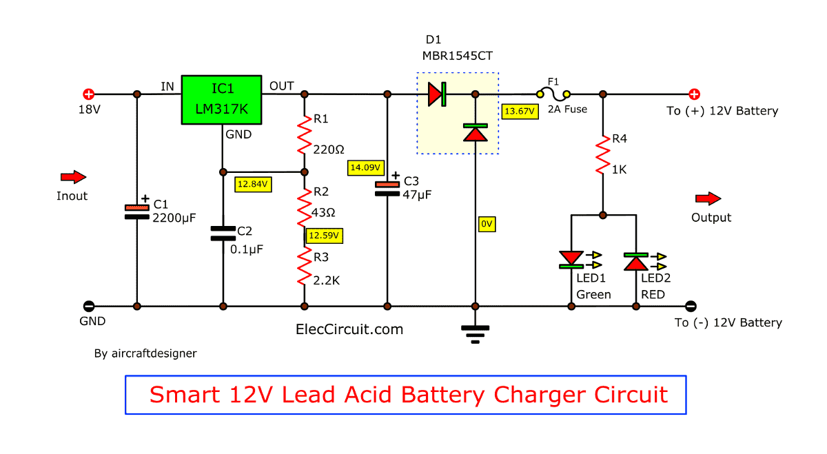
i need help in designing pwm solar lead acid battery charger. I have designed the charger circuit and when i simulated it, it worked and when i constructed it, it failed to charge the 12V battery. I have uploaded the circuit please help me rectify the problem.
 

First question, do you really need the linear regulator? This will destroy your efficiency and since this is a solar powered charger. Where do you get the PWM signal?
 

    raymond86

    Points: 2
    Helpful Answer Positive Rating
thanks for assistin, i guess i have to get rid of the linear regulator, well the pwm wignal will be generated by a PIC16F877A microcontroller. This signal generated is used to control the buck converter in charger circuit. The system will consist of a measuring unit that will measure the battery voltage and a pwm signal will be generated depending on the battery level. if i remove the linear regulator will this solve my problem
 

I am not an expert on solar cells, so my regulation suggestions could be far off. I think that solar cells have a V-I curve unlike that of a battery or an ideal voltage source. The solar cell outputs maximum power at a particular voltage and current demand and if either voltage or current demand is too high, the power supplied by the solar cell drops. This would greatly complicate the design.
 

12v-lead-acid-battery-charger-by-lm317k.gif


here a charger that will work isa
 

Raymond,

First, C2 and C3 are in backwards. The + side of the cap should go to the higher voltage, not to GND. Depends on the capacitor technology, but most polarized caps will be destroyed the way you have them. Could be spectacular, and not in a good way.

Next you need to know the output voltage of the solar cells, and know that a lead acid battery will need about 14.5V to be charged. They are called "12V" but they are not. So the solar cell output must be more than 14.5V plus the linear dropout voltage, which is about 2V for the LM350, plus a bit for drop across the FET. Say, 17V.

As was said, pick either linear or switcher. The switcher should be fine without the linear in front of it.

Lee
 
  • Like
Reactions: djdaga

    djdaga

    Points: 2
    Helpful Answer Positive Rating
eng_msa_8_8 said:
12v-lead-acid-battery-charger-by-lm317k.gif


here a charger that will work isa
This charger will destroy a battery in a potentially dangerous way, since there is no current limiting. A battery that is completely run down, will draw a large amount of current which will cause the battery to overheat.

A transistor is required to measure a current sense resistor and pull the adj pin on the LM317 low when an excessive amount current is drawn. Do not exceed the manufactures charging specializations in terms of charging voltage and current.
 

Status
Not open for further replies.

Similar threads

Part and Inventory Search

Welcome to EDABoard.com

Sponsor

Back
Top