Continue to Site

Welcome to EDAboard.com

Welcome to our site! EDAboard.com is an international Electronics Discussion Forum focused on EDA software, circuits, schematics, books, theory, papers, asic, pld, 8051, DSP, Network, RF, Analog Design, PCB, Service Manuals... and a whole lot more! To participate you need to register. Registration is free. Click here to register now.

view the wave signal of function generator to the pc through

Status
Not open for further replies.

goory

Newbie level 6
Joined
Feb 2, 2010
Messages
11
Helped
0
Reputation
0
Reaction score
0
Trophy points
1,281
Location
malaysia
Activity points
1,365
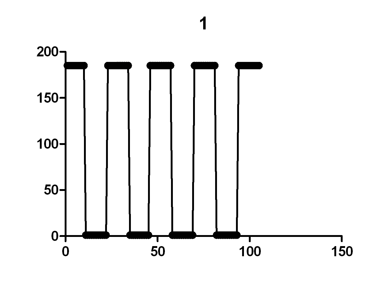
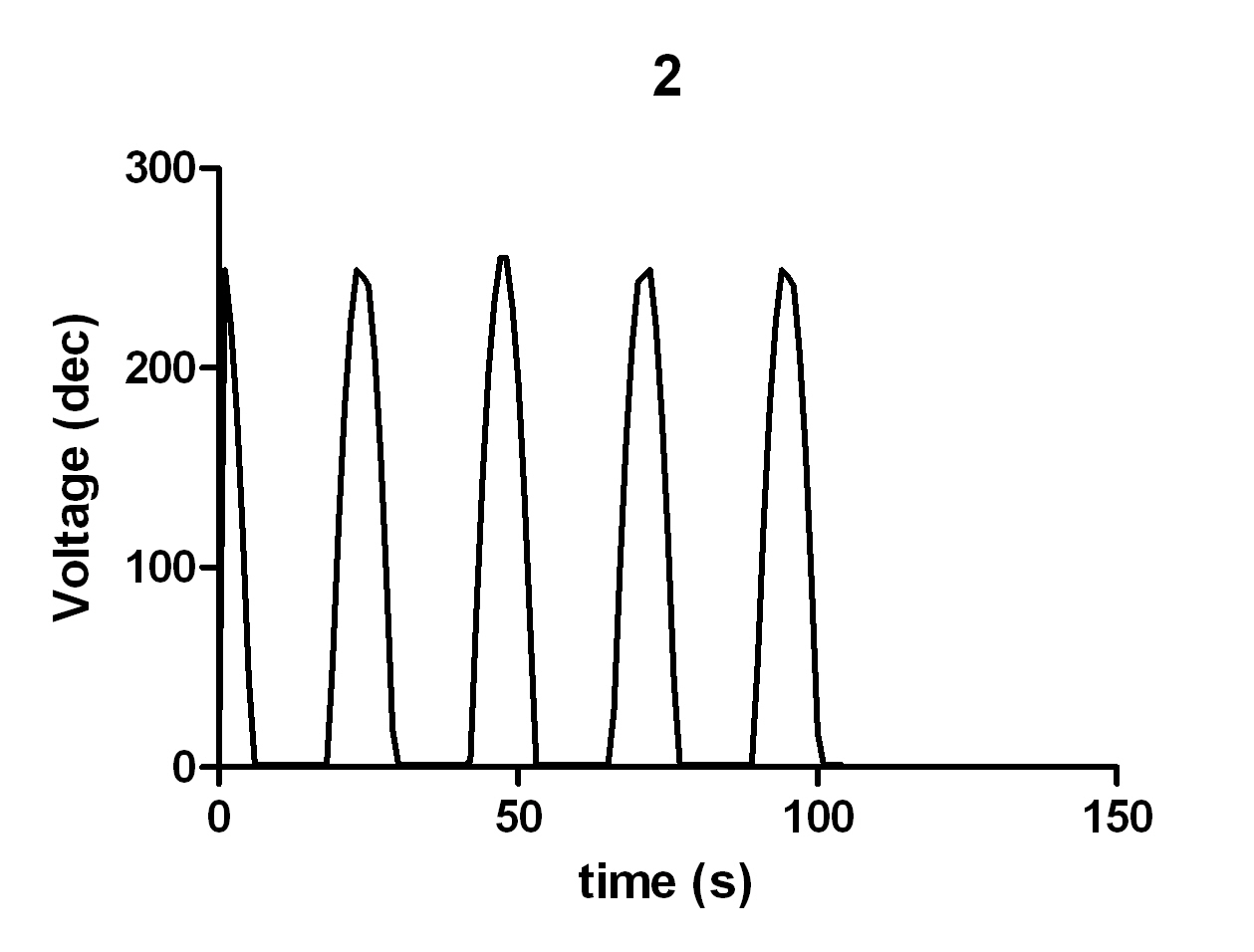
hi! can anyone help me to view the wave signal of function generator to the pc through hyperterminal? i use pic18f4580

can anyone give any idea? i think i will get the value at hyperterminal from ascii code generated and use the value to build wave in matlab or excel.

can anyone give the idea flow of to convert this wave to the value to be seen in hyperterminal?
 

Re: view the wave signal of function generator to the pc thr

Please re-phase your question again.
 

    goory

    Points: 2
    Helpful Answer Positive Rating
Re: view the wave signal of function generator to the pc thr

i used pic18f4580

i want to display the signal from function generator in pc

my idea is to transfer the binary value to hyperterminal and make graph from that value

can u give me the idea to program it in pic? if u have sample assmbly its better.

i already make the assembly to transfer the voltage value to be displayed in DEC value in hyperterminal and the input is the sine wave from function generator;


but the graph plot like this :


thanks 4 ur helps :)
 

Re: view the wave signal of function generator to the pc thr

In that case you should be able to import them directly to excel,
after saving the data from Hyperterminal.
Try the option under Hyperterminal>Transfer.
Open the saved file from excel.
I am not sure if you need a de-limitor for your data stream.
 

    goory

    Points: 2
    Helpful Answer Positive Rating
Re: view the wave signal of function generator to the pc thr

thanks for your helping.

by the way, my coding display the decimal value of voltage in hyperterminal, is there other way to view the voltage value same as input value in the hyperterminal. for example, if the input is 1.5V, so i can display 1.5 at the hyperterminal or else?

thanks again
 

Re: view the wave signal of function generator to the pc thr

Hi,

Do you mean you want to display the 1.5V in a software program
other than Hyper terminal?

Yes you can.
Write your own software to read the data send from your micro-controller.
You can use Visual Basic/C++, Java, etc.. Many many platform/language can do that.
 

    goory

    Points: 2
    Helpful Answer Positive Rating
Re: view the wave signal of function generator to the pc thr

owh, i got it..

if i used the ECG signal as analog input and want to display the ECG graph, is my coding suitable for this situation? or you have any other suggestion?
 

Re: view the wave signal of function generator to the pc thr

There is no strict rule in the protocol format.

You may like to research more in other protocol (industries practise)
and implement the one closer to your needs.

Best Regards,
Siong Boon
 

    goory

    Points: 2
    Helpful Answer Positive Rating
Re: view the wave signal of function generator to the pc thr

thanks for ur helping, i think i got the idea to built up my project.

but, may i asked 1 last question. the input voltage of ecg signal is about 14V. should i altered anythg to the input because is voltage is high for ADC i think?

Added after 34 minutes:

im already build up the square wave and sine wave at the PC from hyperterminal data. its working fine with square wave but didn't have the -ve value of my sine wave. thanks for ur helping


now, i.m working for my ecg input..
 

Re: view the wave signal of function generator to the pc thr

This is a good question.

It is best not to modify/attentuate the signal to sample as original as possible.
Because the process might destroy your signal.
Like what you mention, in practise it may result in extra circuitry.

Some ADC allow configuration to digitise a wider range of voltage level.
Even in PIC microcontroller, which uses 5V,
the ADC itself, if I can remember correctly, can
also sample signal at a wider voltage by setting the reference voltage.

Sampling the attenuated signal simply means the loss in resolution.
In order to achieve better resolution after attenuation,
a higher bit ADC helps but to certain extend.
It is much more difficult to sample low amplitude signal,
for it behavior much like noise.

You have to decide what you want.
If the modification to your signal do not affect your application,
by all means attenuate your signal....
as much as possible try to preserve the original signal form.

Sincerely,
Siong Boon
 

    goory

    Points: 2
    Helpful Answer Positive Rating
Hi,
I dont know more higher input range as +/-10V for ADCs, also you need so & so an attenuator!
If your resistors are not very high ohmic, your signal will be not destroyed through parasitic capacitor effects to the resistors, otherwise is an attenuator light to compensate_you have it in all oscope probe i.e....
Clear, the used range is up to maximum amplitude to use, but the signal can (& must) be attenuated for 5 or 10V absolut max. peak_depending your input range.....
K.
 

    goory

    Points: 2
    Helpful Answer Positive Rating
Re: view the wave signal of function generator to the pc thr

thanks for the really needed knowledge for me and i appreciate it.

now, im already run on my ecg signal. but the signal on the negative part cannot be display because my assembly just convert the analog input to decimal value to be sent to hyperterminal. it is same with the sine wave before.


is there any way i can get the value of the negative part of the signal?

this is the ecg waveform..


thanks..

Added after 9 minutes:

if there any sample code that similar to show the wave maybe can be helped
 

:)
welcome!
I think you have an offset on the signal, because the "zero line" noises arnt to see & seems it has more catted of as only negatives...
Otherweise ,& in my opinion, you dont have a SW solution for your "negative" number handlings; apply a extra (buffer)amplifier before PIC and do offset adding with it to the input signal...PIC is unipolar & your ECG-signal is bipolar!
If you do check your sample ECG over their notes: you has ca. 30 counts for full ecg pp signal_ from that is ca. 30% in "negative part"!
[signal range: 76/84(second + pulse92) & 104]
I wish to tell only; your full signal has (peak-peak) ca. 30% in negative, what is to offset into the ADC range_than PIC has a range (as I know) 0...+5V & these means, that you must shift/offset the input signal into positive range, all over zero Volt.
If somebody wrote it already-sorry.
K....
 

    goory

    Points: 2
    Helpful Answer Positive Rating
Hali,
Maybe it helps for you:
Pic ADC - Negative voltages. #1252942
 

    goory

    Points: 2
    Helpful Answer Positive Rating
Re: view the wave signal of function generator to the pc thr

thanks for the really help link.

i will try with my ecg signal..

thanks
 

Re: view the wave signal of function generator to the pc thr

Hi all helper :)

Sorry for the late update, i'm buzy with my report writing.

yes, ur idea really work. when i shifted the signal with dc current. the siignal can easily be captured by PIC. it's maybe simple but not for new one like me :)

Thanks again for both of u for helping me :) best regards... :D


Hi!
:) your welcome, tnx for FB!
I didnt understand you; was the idea with SW solution for negative input range on PIC wrong?
Others: important is, that you are on good way!
Have good progress!
Greetings!
K.
 

    goory

    Points: 2
    Helpful Answer Positive Rating
Status
Not open for further replies.

Part and Inventory Search

Welcome to EDABoard.com

Sponsor

Back
Top