Continue to Site

Welcome to EDAboard.com

Welcome to our site! EDAboard.com is an international Electronics Discussion Forum focused on EDA software, circuits, schematics, books, theory, papers, asic, pld, 8051, DSP, Network, RF, Analog Design, PCB, Service Manuals... and a whole lot more! To participate you need to register. Registration is free. Click here to register now.

Voltage Multiplier Circuits - Need help with Theory of op

Status
Not open for further replies.

ngmedaboard

Member level 3
Joined
Feb 7, 2010
Messages
60
Helped
7
Reputation
14
Reaction score
4
Trophy points
1,288
Location
United States
Activity points
1,831
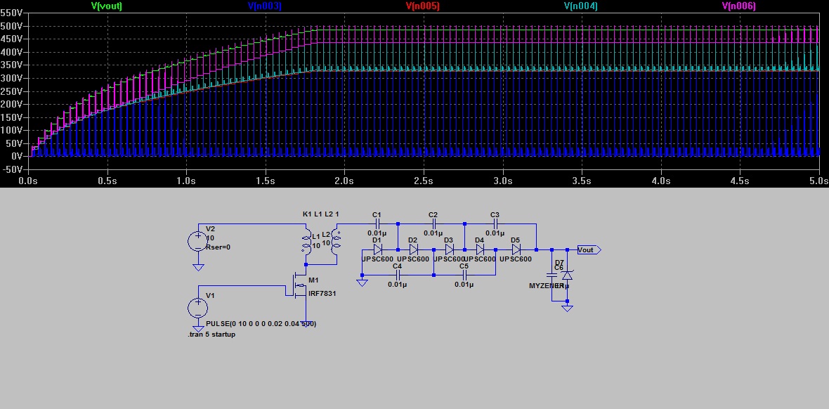
I'm developing a circuit that requires a voltage multiplier that can boost about 12V up to about 500V both DC. I had one solution based on a daisy chain of voltage doublers aka a villard cascade. I think I understand the basics of that approach but came across a circuit online that seems to multiply voltage in substantially fewer stages. I'm having some trouble analyzing it and was wondering if someone might be able to explain the theory of operation of such a design (also any limitations or pros and cons between the two shown).

**broken link removed**

Thanks!

-NGM
 

Re: Voltage Multiplier Circuits - Need help with Theory of o

I cannot view the image
 

Re: Voltage Multiplier Circuits - Need help with Theory of o

Ok, fixed the image. Try it now, sorry about that, not sure why the file saved to a format not readable by all programs.
 

Re: Voltage Multiplier Circuits - Need help with Theory of o

Both circuits rely on flyback operation. In principle, you can achieve 500 V with a single diode. The first circuit is a trippler, the second
a doubler cascade. As in the second circuit, you can omit C5 and D5 in the first circuit without changing it's operation or the waveforms
considerably.

"No clamp needed" simply means, that either the unregulated output voltage is 500 V by chance, or a feedback loop is involved.
 

Re: Voltage Multiplier Circuits - Need help with Theory of o

I'm confused you mentioned C5 and D5 can be eliminated in the second circuit but there is no D5 in the second cicuit.

In any case the way I somewhat understand the first is that we have a whole chain that adds an AC coupled pulse to the DC at each stage and then rectifies it.

I'm still struggling to understand the whole sequence of events on the second circuit as I think if I did to your point, I'd be able to create almost any ratio I needed. I'll research voltage tripplers.

In terms of the no clamp needed, that was just my own note, observation.

-NGM

Added after 7 minutes:

Also, even as a trippler, that still wouldn't get our 5V near 500V?
 

Re: Voltage Multiplier Circuits - Need help with Theory of o

I'm confused you mentioned C5 and D5 can be eliminated in the second circuit.
??? I said: "you can omit C5 and D5 in the first circuit"
The respective function has already been removed in the second circuit, but it doesn't change much to it.

Also, even as a trippler, that still wouldn't get our 5V near 500V?

The output voltage of a flyback circuit is limited only by the non-ideal device parameters, particularly transistor and diode
switching losses, also transformer leak inductance.

You apparently assume, that the changes to the second circuit involve some mysterious performance improvement. That's not
the case. To achieve a higher flyback voltage ratio, the second circuit must mainly use a good, fast controlled switch transistor.

In my opinion, it's far from a reasonable design to use a 1:1 transformer and 1N4007 as rectifier diodes. But I assume
that it still can work.

My favourite design would be e.g. a 1:10 transformer and a single (fast) rectifier diode. For higher output voltages than 500V,
a mutiplier cascade would be suitable to reduce the transformer output voltage.
 
Re: Voltage Multiplier Circuits - Need help with Theory of o

For VM A: 3-stage Cockroft-Walton (CW) multiplier providing 3x gain on the secondary side. What's the 10M for? It seems to be only increasing the output impedance of the CW multiplier stage. And contrary to what FvM has mentioned, omitting C5 and D5 would result in 0.5x less gain.

For VM B: Just a Dickson Pump doubler on the secondary side, providing 1.5x gain.
The FET, Transformer, D2 and C4 forms a standard flyback cell.
C5, D3 and D4 forms a one-stage dickson pump.
C6 is the output cap.


So assuming
1. Transformer secondary voltage pulse are the same, ie equal input voltage, equal duty cycle and equal Ton
2. Ignoring stray capacitances which reduces the effectiveness of the VMs,

VM A should provide twice the output voltage compared to VM B.
 

Re: Voltage Multiplier Circuits - Need help with Theory of o

Yes, my error with regard to the D5, C5 (sorry a bit tired).

I agree, I was wondering the same thing, why they didn't use a transformer for step up instead of just isolation. Then rectify the output. (Did you mean a 1:100?) I suspect it could be difficult to find a step up transformer with the correct ratio in a nice small package (I believe the current I need post rectification is in on the order of about 5uA's so high output impedance is tolerable.)

I am looking at switching an IRF830 N-FET at present at about 50Hz.
**broken link removed**
My duty cycle is in the ball park of 50:50 but isn't perfect.

The output voltage of a flyback circuit is limited only by the non-ideal device parameters, particularly transistor and diode
switching losses, also transformer leak inductance.

I don't quite understand the reference to flyback, I don't see how a voltage doubler could do more than double it's input peak to peak voltage, the same goes for a trippler. When I think of flyback, I think of using a rapid di/dt over a coil to create a high peak to peak voltage spike, be it an inductor a transformer winding. The kind of circuit you use to generate spark or in a CRT television or monitor. The only coil in this circuit is the isolation transformer that is doing nothing other than isolation.

-NGM[/url]

Added after 7 minutes:

checkmate said:
For VM A: 3-stage Cockroft-Walton (CW) multiplier providing 3x gain on the secondary side. What's the 10M for? It seems to be only increasing the output impedance of the CW multiplier stage. And contrary to what FvM has mentioned, omitting C5 and D5 would result in 0.5x less gain.

For VM B: Just a Dickson Pump doubler on the secondary side, providing 1.5x gain.
The FET, Transformer, D2 and C4 forms a standard flyback cell.
C5, D3 and D4 forms a one-stage dickson pump.
C6 is the output cap.


So assuming
1. Transformer secondary voltage pulse are the same, ie equal input voltage, equal duty cycle and equal Ton
2. Ignoring stray capacitances which reduces the effectiveness of the VMs,

VM A should provide twice the output voltage compared to VM B.

If the gain for the first circuit is only 3X, how does it take a 12V pk - pk and bring the unclamped output >500V? Similar question applies to the second circuit. Do we agree that the secondary coil on the isolation transformer mirrors that of the primary?
 

Re: Voltage Multiplier Circuits - Need help with Theory of o

omitting C5 and D5 would result in 0.5x less gain.
No. You don't consider the extreme unsymmetric voltage relation of flyback versus forward voltage. "Gains" of 0.5 are
only valid with symmetric input voltages, not with flyback operation.

You would loose only 12V of achievable output voltage. C5/D5 is only recovering the (rather low) forward voltage of 24V, but
you loose 12 V supply offset. I can't calculate the exact voltages for the six trippler, because the 10M voltage drop is
unknown. But for the 3 diode circuit, the relations are as follows
(assuming ideal diodes):
- forward voltage 10V
- flyback voltage 242.5V
By supplementing C and D to a full doubler circuit, you get just 5V more output voltage.
 

Re: Voltage Multiplier Circuits - Need help with Theory of o

10M voltage drop shouldn't be that great as we are only pulling a few uA through it.
 

Re: Voltage Multiplier Circuits - Need help with Theory of o

I correct myself. I failed to see that terminal 3 of your transformer is not connected to GND, as per the usual flyback configuration. Assuming the drain voltage of the FET is a pulse of 0-Vp.

For VM A, FvM is right that C5 and D5 are redundant. The output voltage will be (3Vp -24).

For VM B, the output voltage will be just Vp.

If you connect the transformer like what I mentioned previously, then my previous analysis holds, and you will find higher outputs.

Added after 2 minutes:

ngmedaboard said:
10M voltage drop shouldn't be that great as we are only pulling a few uA through it.
We want supplies to have a low output impedance not because of voltage drops, but for it to be responsive to changes in loading conditions.
 

Re: Voltage Multiplier Circuits - Need help with Theory of o

The 10 MΩ resistor in the zener stabilizer circuit is O.K. for an effectively no load operation, e.g. with some photo detectors.
But it's only meaningful with unregulated (fixed duty cycle or peak current controlled) flyback operation. A voltage
control loop would be a smarter solution.
 

Re: Voltage Multiplier Circuits - Need help with Theory of o

The low side of both the primary and secondary coils are tied to one another. Yet both circuits are in production products and claim >500V output with either a 12V in the case of the first circuit or 5V pk switching on the input to the primary.
 

Re: Voltage Multiplier Circuits - Need help with Theory of o

From the pin numbering, I expected that 2 and 4 are same polarity, e.g. "low side". Otherwise, the output voltage
would be very low. An unequivocal polarity sign should be better shown in the circuit symbol.
 

Re: Voltage Multiplier Circuits - Need help with Theory of o

No, no pins 2 and 3 are tied together and thus of the same polarity. 1 and 4 are of the positive sides of their respective coils.

Added after 2 hours 47 minutes:

From the pin numbering, I expected that 2 and 4 are same polarity, e.g. "low side". Otherwise, the output voltage
would be very low. An unequivocal polarity sign should be better shown in the circuit symbol.

I take that back, you may be right with regard to the transformer polarity.

At least in the case of the first circuit I think the output may in fact be swinging inversely to that of the primary. In other words the primary + is 5V dc, primary - is 0V to 5V, then the secondary tied to primary- obviously is 0V to 5V as well, while the other secondary output is perhaps 0V. Make sense?

I think that makes at least the first circuit make a little more sense. We can think of the input to the transformer as a wave of 0 to 5V with the output as 0 to -5V, assuming the negative lead of your measurement device is connected to the common connection.
 

Re: Voltage Multiplier Circuits - Need help with Theory of o

Alright I spiced the first circuit out. LTSpice is nice!


Given the difficulty of making direct measurements (due to loading down), I decided to simulate the circuit. I took a wild guess on the transformer reactance though that I suspect could be way off. I am happy to provide the spice model for anyone interested.

I do have a question that I could use some help on, do any of you know how to do a proper reactance calculation for the following transformer?

https://www.sparkfun.com/datasheets/Components/General/TTC-105.pdf

Thanks
 

Re: Voltage Multiplier Circuits - Need help with Theory of o

The transformer datasheet doesn't contain th einformation to calculate or even estimate inductances (main and leakage). You have to measure it.

I see, that the transformer has a rather high DC resistance. That's the price of the lower cut-off frequency requested for a telcom
application. I would prefer a transformer with less inductance and operate it at a higher switching frequency. It results in smaller
size and higher efficiency.

If you love low inverter frequencies, you may want to use a small mains frequency print transformer (e.g. 0.35 VA) in
reverse connection for your DC/DC. It already has a considerable built-in step up ratio and can easily achieve 500 V with a
simple doubler rectifier. It works best up to a few 100 Hz switching frequency.
 
Re: Voltage Multiplier Circuits - Need help with Theory of o

If one were using a duty cycle significantly less than 50% on time, would that mean the voltage would less than double?
 

Re: Voltage Multiplier Circuits - Need help with Theory of o

moving last post to a new topic.
 

Status
Not open for further replies.

Similar threads

Part and Inventory Search

Welcome to EDABoard.com

Sponsor

Back
Top