powersys
Advanced Member level 1
This problem has been haunting me for several months. Kindly advise.
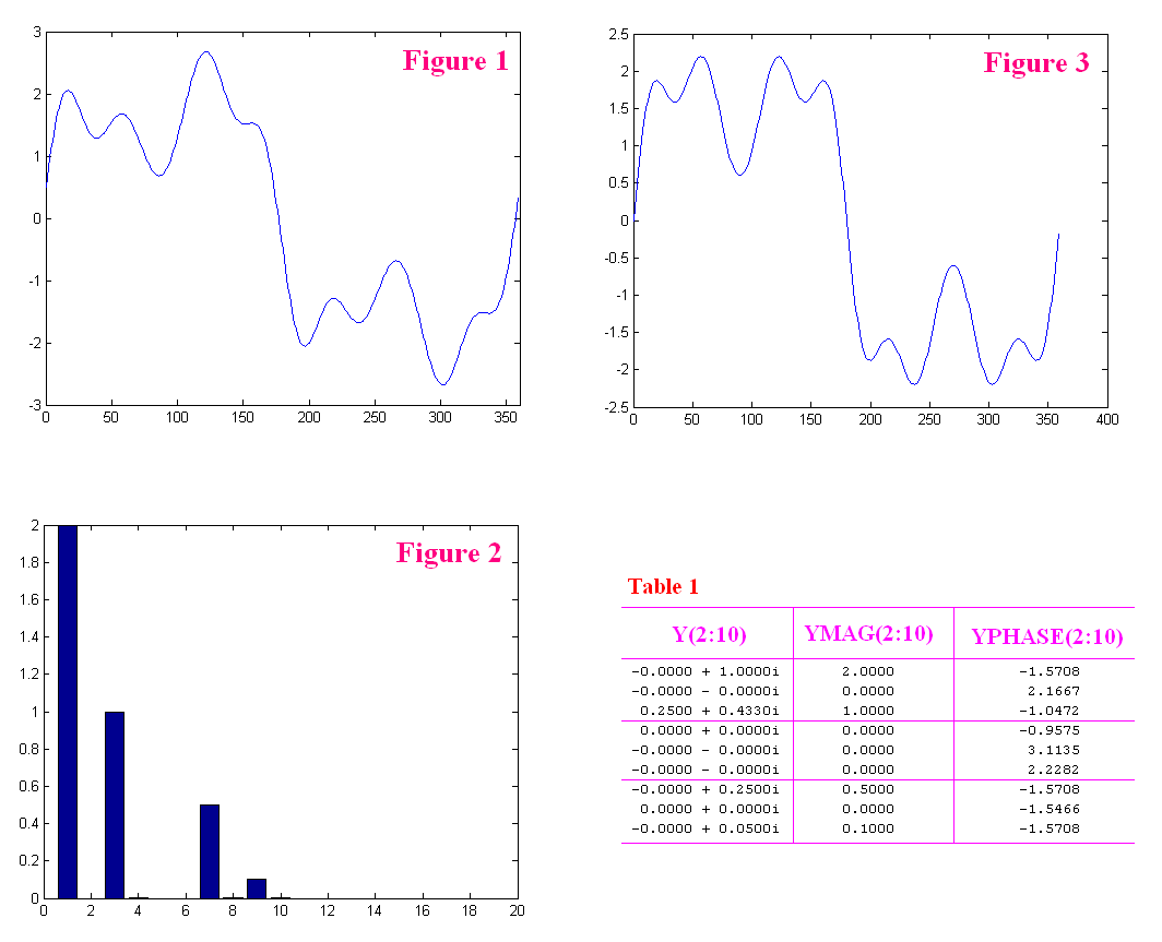
Let's say a user is given a dataset of signal as shown in Figure 1.
Assume that he doesn't know how the signal is created (i.e. he doesn't know the codes in Part-A).
He performs FFT on the signal (using Part-B code) and the results he obtains are given in Figure 2 and Table 1 (only harmonics 2-10 are shown).
Clearly, he finds out there are 4 major harmonics in the signal, i.e. 1st, 3rd, 7th, and 9th.
Although there are some little values at 4th, 8th, and 10th, he decides to assume that the magnitudes of these harmonics are zero.
He was taught that a signal can be constructed by a series of sinusoids.
Since he knows the magnitudes of major harmonics, he thinks he can reconstruct the signal using code in Part-C (assume there is no Matlab ifft function).
However, he soon finds out the reconstructed signal (as shown in Figure 3) is not similar to that in Figure 1.
Why?
Questions:
[1] Is the code performed in Part-C to reconstruct the signal correct?
[2] Are those information (especially Y(2:10) and YPHASE(2:10)) given in Table 1 useful in signal reconstruction? If YES, how can we use them correctly?
Thank you very much
Code:
%%%%%%%%%%%%%%%%%%%%%%%%%%%%%%%%%%%%%
% PART-A: To create signal
%%%%%%%%%%%%%%%%%%%%%%%%%%%%%%%%%%%%%
x = (0:1:359);
y1 = 2*sin(x*pi/180);
y3 = 1*sin(3*x*pi/180 + 30/180*pi);
y7 = 0.5*sin(7*x*pi/180);
y9 = 0.1*sin(9*x*pi/180);
y=y1+y3+y7+y9;

figure(1);
plot(x,y); xlim([0 360]);
%%%%%%%%%%%%%%%%%%%%%%%%%%%%%%%%%%%%%


%%%%%%%%%%%%%%%%%%%%%%%%%%%%%%%%%%%%%
% PART-B: To compute the FFT of the signal
%%%%%%%%%%%%%%%%%%%%%%%%%%%%%%%%%%%%%
N=length(y);
Y=fft(y)/N;

YMAG=2*abs(Y);
YPHASE=angle(Y);
realY=real(Y);
imagY=imag(Y);

figure(2);
bar(YMAG(2:20));

[Y(2:10)' YMAG(2:10)' YPHASE(2:10)']
%%%%%%%%%%%%%%%%%%%%%%%%%%%%%%%%%%%%%


%%%%%%%%%%%%%%%%%%%%%%%%%%%%%%%%%%%%%
% PART-C: To reconstruct the signal
%%%%%%%%%%%%%%%%%%%%%%%%%%%%%%%%%%%%%
rcy1 = YMAG(1+1)*sin(1*x*pi/180);
rcy3 = YMAG(1+3)*sin(3*x*pi/180);
rcy7 = YMAG(1+7)*sin(7*x*pi/180);
rcy9 = YMAG(1+9)*sin(9*x*pi/180);
rcy  = rcy1+rcy3+rcy7+rcy9;

figure(3);
plot(x,rcy);
%%%%%%%%%%%%%%%%%%%%%%%%%%%%%%%%%%%%%") .
.