Continue to Site

Welcome to EDAboard.com

Welcome to our site! EDAboard.com is an international Electronics Discussion Forum focused on EDA software, circuits, schematics, books, theory, papers, asic, pld, 8051, DSP, Network, RF, Analog Design, PCB, Service Manuals... and a whole lot more! To participate you need to register. Registration is free. Click here to register now.

a question about a simple current mirror

Status
Not open for further replies.

Fractional-N

Full Member level 1
Joined
Oct 15, 2007
Messages
97
Helped
2
Reputation
4
Reaction score
2
Trophy points
1,288
Activity points
2,071
27_1257754517.jpg


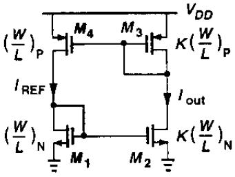
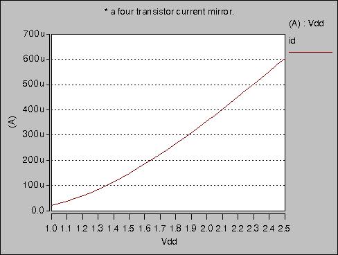
this circuit can support any current level.
if i simulate the circuit, resulting Iref current equals 265.8u
can you tell me what happens in the circuit and how this current is being formed?


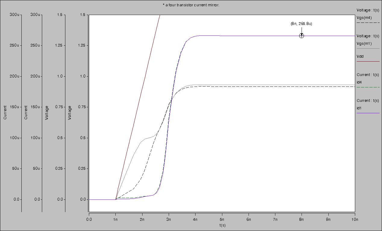
here is the simulation results. supply voltage reaches 1.8v in 2ns.
 

This circuit has is made of two current mirrors: pmos and nmos. You have only equation Iout=kIref, which means that current ratio could be controlled, but not current value. To make this circuit usable you need resistor between source of M2 and ground to define current and also start-up circuit.
 

    Fractional-N

    Points: 2
    Helpful Answer Positive Rating
thanks pixel
I know we cannot control the current value. my question is: for a given (W/L) ratios and supply voltage, why the output current is 265.8u?
you know, since there is no way to control the current, i thought in every simulation the current should be a different value; or with different slopes for supply voltage ramp different currents should result.
simply: Is there a way to calculate the current, given the (W/L) ratios and supply voltage?
 

In this case you should not much beleive to simulator. It depends on initial conditions of parasitic capacitances.
Try rise time of 1ms or 1s, or put at the left side some parasitic capacitance.
You can also switch on and off power supply with some period... etc...
 

    Fractional-N

    Points: 2
    Helpful Answer Positive Rating
Well, I simulated the circuit many times with different situations, different rise times and different "initial condition" voltages at nodes. Also simulated the circuit with very small sources connected to some nodes (representing noise sources)
although the transient response changes in each case, the final (steady state) current value is the same 265.8u !

By the way, you are saying if i implement the circuit in real world, the current is not a distinct value. And each time i connect the supply voltage I will get a different current. Despite what simulators show. Right?
Maybe there is something that is not modeled (or correctly modeled) in simulator
?

I know my question is somehow abstract, I'm just curious :D
 

I dont know which simulator and models do you use, but you have to recognize such conditions when you should not beleive them. This circuit is right example. Similarly in fully differential circuit with pmos nmos operating point is poorly controled, whatever simulator shows you. Normaly such effects you should model and easily get in simulations.
Have you tried to change power supply voltage.
 

    Fractional-N

    Points: 2
    Helpful Answer Positive Rating
Have you tried to change power supply voltage.
yes, and the current shows a strong dependence on supply voltage.
:?: :D now what does it mean? what should I conclude?

86_1257845490.jpg
 

That means you probably do not need such bias circuit. You could achieve similar results with diode connected nmos and resistior between VDD.
Put some resistance between source of M2 and ground.
 

    Fractional-N

    Points: 2
    Helpful Answer Positive Rating
These are not ideal current mirrors, and nonidealities
set the "current that works". Such as on resistance for the
available headroom, etc. It bootstraps up on leakage
and keeps on going until it "bumps its head" because
the non-diode-connected MOS have greater than unity
mirror-gain when Vds>Vgs.
 

    Fractional-N

    Points: 2
    Helpful Answer Positive Rating
dick_freebird

can you explain, what do you mean by "bumps its head"?
 

Relying on leakage or capacitive coupling for start-up is a recipe for disaster.

The current will increase until it is limited by the device impeadances. Bumps it's head means no more headroom.

This circuit is very process, temperature, and supply dependent don't use it.
 

    Fractional-N

    Points: 2
    Helpful Answer Positive Rating
Status
Not open for further replies.

Similar threads

Part and Inventory Search

Welcome to EDABoard.com

Sponsor

Back
Top