Continue to Site
Follow along with the video below to see how to install our site as a web app on your home screen.
Note: This feature may not be available in some browsers.
ganes said:hi,
Can someone tells me how X(K) change f we doubled the sampling freuqency
") signal to quantization signal = 6 sin (3πt)-5cos (6πt)+7cos(8πt +π/6)
signal to quantization signal = 6 sin (3πt)-5cos (6πt)+7cos(8πt +π/6) 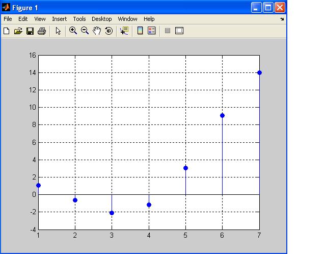
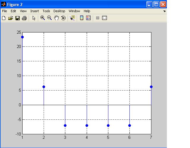 = 6 sin (3πt)-5cos (6πt)+7cos(8πt +π/6) with 4 quantization level using trancated technique.. and the dynamic range is ±10V..