Continue to Site

Welcome to EDAboard.com

Welcome to our site! EDAboard.com is an international Electronics Discussion Forum focused on EDA software, circuits, schematics, books, theory, papers, asic, pld, 8051, DSP, Network, RF, Analog Design, PCB, Service Manuals... and a whole lot more! To participate you need to register. Registration is free. Click here to register now.

What does Rds(on) in a MOSFET mean?

Status
Not open for further replies.

eliben

Newbie level 5
Newbie level 5
Joined
Jul 12, 2007
Messages
10
Helped
1
Reputation
2
Reaction score
1
Trophy points
1,283
Location
Israel
Activity points
1,374
Hello,

I'm having a slight confusion over what Rds(on) means for a MOSFET.
In the book it says that Rds(on) is the resistance (Vds / Ids) in the linear (triode) region. After the FET enters saturation, the resistance obviously changes as the current stays the same for increasing voltage.

However, people I ask say that they only use FETs for switching (i.e. either cutoff or saturation), and for them Rds(on) is the resistance in saturation.

Which is right? Can you point to a lucid explanation of this topic?
Thanks in advance
 

rdson

In saturation region,it's small signal resistor,which is also called ro=1/gds.It's usually designed to be very large because we want to get a large gain
Av=gm*ro
In linear region,the resistance of a MOSFET is called Rds(on).it's designed to be very small because We use MOSFET as a switch.
 
rdson wiki

Rds(on) is the resistance when the device is in saturation.

Rds in a linear region is of no significance (meaning?) because it changes as Id / Vds changes.
 

rdson temperature coefficient

millwood said:
Rds(on) is the resistance when the device is in saturation.

Rds in a linear region is of no significance (meaning?) because it changes as Id / Vds changes.

Aren't you confusing the regions here?

The linear (triode) region is where Rds is relatively constant, in the saturation region Vds rises without Id rising, so the resistance is changing.
 
  • Like
Reactions: ashare

    ashare

    Points: 2
    Helpful Answer Positive Rating
measuring mosfet rdson

From what i know Rdson is measured when the mosfet is fully opened .
The only change in resistance you will wittnes is due to the positive temperature coefficient of the mosfet .
(hot mosfets have a slightly higher resistance)
In the *triode* region you can regulate the *resistance* with Vg ,your resistance depends on Vg.
Assuming you can keep the mosfet temperature stable ,then your Rds will be as stable as your gatevoltage .
In the switch state you either have very high resistance(closed) or Rdson like stated in the datasheets when its fully opened .
Do keep in mind to fully open a mosfet a gatevoltage of 10 to 15 volt is needed (logic mos excluded).
(Rdson stated in the datasheet is at 25 degree celcius and is usualy also noted at 75 or 100 degree)
Have a look at page 5 of this datasheet and it should take your doubts away .
http://www.irf.com/technical-info/appnotes/an-957.pdf
It describes how to measure your Rdson and also how they specify it .
http://www.irf.com/technical-info/appnotes/mosfet.pdf
The last datasheet describes in detail what composes your Rdson (and other parameters ).
Usualy most of those factors are of no concern ,but this datasheet does answer all your questions about Rdson and what it consists of.
 

    eliben

    Points: 2
    Helpful Answer Positive Rating
mosfet rdson

walkura said:
From what i know Rdson is measured when the mosfet is fully opened .
The only change in resistance you will wittnes is due to the positive temperature coefficient of the mosfet .
(hot mosfets have a slightly higher resistance)
In the *triode* region you can regulate the *resistance* with Vg ,your resistance depends on Vg.
Assuming you can keep the mosfet temperature stable ,then your Rds will be as stable as your gatevoltage .
In the switch state you either have very high resistance(closed) or Rdson like stated in the datasheets when its fully opened .
Do keep in mind to fully open a mosfet a gatevoltage of 10 to 15 volt is needed (logic mos excluded).
(Rdson stated in the datasheet is at 25 degree celcius and is usualy also noted at 75 or 100 degree)
Have a look at page 5 of this datasheet and it should take your doubts away .
http://www.irf.com/technical-info/appnotes/an-957.pdf
It describes how to measure your Rdson and also how they specify it .
http://www.irf.com/technical-info/appnotes/mosfet.pdf
The last datasheet describes in detail what composes your Rdson (and other parameters ).
Usualy most of those factors are of no concern ,but this datasheet does answer all your questions about Rdson and what it consists of.

Thanks, the links look helpful.

But is it correct to say that the MOSFET is used as a switch in triode, and not in saturation?
 

what is mosfet rds on

No its the other way around .
The triode or lineair region as its also called is the region where the mosfet acts as a (regulating) resistor .

The saturation or active mode is when the mosfet is fully opened
(the resistance it presents in this mode is the Rdson from the datasheets .)

You can build a simple test with a 12 volt supply .
connect a potentiometer from plus to minus washer to the gate (lets say 10 Kohm).
(the value doesnt matter much as long as the current through the potentiometer doesnt make it get hot)
Connect a little 12 volt lightbulb between the plus and drain of the mosfet (source to minus)
This way you can measure both regions of the mosfet .
When you take a small bulb like for bicycles and (if needed) a small radiator for the mosfet you can measure without any risk for your parts .
I know that IRF has a mosfet application guide on its website but i couldnt find it for you this fast .
That book gives a more easy explanation .


Good luck .
 

calculating fet rdson area

When a transistor is opened (high Vgs voltage, high current, low resistance) - it operates in the linear (not saturation) region.

Attached diagram illustrates where the operating points for On state and OFF state are on Ids-Vds plot.
 
fet rds

timof said:
When a transistor is opened (high Vgs voltage, high current, low resistance) - it operates in the linear (not saturation) region.

Attached diagram illustrates where the operating points for On state and OFF state are on Ids-Vds plot.

the transition from the "off" state to the "on" state is gradual. typically you will see a Vgs(th) parameter in the datasheet. you can see that in your chart, between the traces.

as Vgs goes up, the mosfet starts to conduct, as you can see in a typical Id vs. Vgs chart (with Vds fixed but Vds isn't that big of a factor here). This is called the linear region because the mosfet's Id vs. Vgs relationship can be "linearized" via a source resistor, for example. Mosfet dissipates considerable amount of heat in this region, and this is where you use a mosfet for amplification.

As you continue to increase Vgs, the mosfet goes into saturation where it functions more or less like a resistor between its D and S pins - thus the Rds(on) parameter dominates.

in saturation, Vds is very low because Rds(on) typically is very low so the mosfet dissipates little power.

a typical vertical mosfet turns on at Vgs=3-4v, and goes into saturation after Vgs > 5 - 6v - we typically drive them at Vgs=10v.

a logical mosfet turns on at Vgs=2v, and goes into saturation at Vgs > 4v.

a lateral mosfet usually goes on at Vgs=1v. Those guys have high Rds(on) so they are typically NOT used for linear applications.
 

wiki transistor mos rds

Region of operation of a MOSFET with low Vds and high Vgs (Vgs>Vt), where transistor behaves as a resistor - current is linearly increasing with voltage - is called LINEAR REGION.

Region with high Vds, where device current is constant or slowly increasing with Vds is called SATURATION REGION.

You can find this definition in any textbook on semiconductor device physics, for example - S.Sze, Physics of Semiconductor Devices, chapter 8 (MOSFET), p. 438 (figure 7), Wiley, 1981.
 

rds on mosfet wiki

if you want to look at your chart, the saturation region is one where the traces are going up: where Vds is very low and Ids goes up with Vds, given a Vgs. the left most region where you put the "on" state symbol.

the linear region is where Vds is significant and does NOT vary with Id. Instead, Id goes up and down with Vgs. That's the middle area where the traces are flat.

the "off" area is where Vgs is < Vgs(th).

Added after 4 minutes:

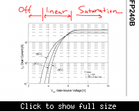
another way to look at the same thing is to look at its Id vs. Vgs chart: from irfp240.

the left most region is where Vgs<Vgs(th), so the device remains off (Id is very small).

as Vgs goes above Vgs(th), the mosfet starts to conduct and its Id goes up with Vgs. this is the linear region.

As Vgs continues to go up, Id stops increasing as the mosfet is "saturated".

the same thing holds for bjt as well.


Added after 34 seconds:

and you can find the same relationship in ALL mosfet datasheets.
 

fet switch high current rdson

Wow, there definitely seems to be a fundamental confusion here - people are bringing up completely different opinions.

I think there is little doubt as to which region is called what - this is by definition (linear (ohmic) is where current rises with Vds, saturation is where current doesn't change with Vds and only depends on Vgs).

However - the question remains: in which region is the MOSFET emloyed as a switch?

Here's a quote from wikipedia, with my emphasis:

Single-type MOSFET switch

This analog switch uses a four-terminal simple MOSFET of either P or N type. In the case of an N-type switch, the body is connected to the most negative supply (usually GND) and the gate is used as the switch control. Whenever the gate voltage exceeds the source voltage by at least a threshold voltage, the MOSFET conducts. The higher the voltage, the more the MOSFET can conduct. An N-MOS switch passes all voltages less than (Vgate–Vtn). When the switch is conducting, it typically operates in the linear (or Ohmic) mode of operation, since the source and drain voltages will typically be nearly equal.

In the case of a P-MOS, the body is connected to the most positive voltage, and the gate is brought to a lower potential to turn the switch on. The P-MOS switch passes all voltages higher than (Vgate+Vtp). Threshold voltage (Vtp) is typically negative in the case of P-MOS.

A P-MOS switch will have about three times the resistance of an N-MOS device of equal dimensions because electrons have about three times the mobility of holes in silicon.

Note the bold part.
Can we agree that this settles the argument? Or is Wikipedia wrong here?
 

mos linear region rds

When you use a mosfet as a switch you try to saturate the channel fully .
Using it in the ohmic region only creates unnessecary heat .
I almost never used mosfets in the triode mode .
As gate voltage i tend to use 12 to 15 Volt to be very sure the mosfet is open as far as possible .
(usualy i use non logic level mosfets .)
For switching you want the mosfet to be in a state with as little as possible resistance .

(just to prevent confusion like last night)
At school they said that a transistor or mosfet is called saturated when a further increase of base or gate voltage doesnt result in a further increase of Ic or Id.
In other words its fully opened .
 

fet rdson temperature coefficient

walkura said:
When you use a mosfet as a switch you try to saturate the channel fully .
Using it in the ohmic region only creates unnessecary heat .
I almost never used mosfets in the triode mode .
As gate voltage i tend to use 12 to 15 Volt to be very sure the mosfet is open as far as possible .
(usualy i use non logic level mosfets .)
For switching you want the mosfet to be in a state with as little as possible resistance .

(just to prevent confusion like last night)
At school they said that a transistor or mosfet is called saturated when a further increase of base or gate voltage doesnt result in a further increase of Ic or Id.
In other words its fully opened .

I think you're still in confusion. The minimal amount of heat is dissipated in triode, where Id is proportional to Vds. When you get into saturation, the voltage rises without any additional current, and you're just increasing the power dissipated over the transistor.

A high Vgs is given precisely to keep the FET in triode for large currents.
 

resistance of a mosfet graph

In itself i think there was no confusion last night ,there were 3 people saying the same in their own words .
Have a look at the graphic from wikipedia ,
(its a crappy source of info but this graph is standard(for n-mosfet)
https://en.wikipedia.org/wiki/File:IvsV_mosfet.png
When you want to amplify (class B) or dim you need to keep the mosfet in the lineair region .
A variating voltage on the gate will give a variating Vds due to the changing resistance of the mosfet channel (higher gatevoltage > lower Rds > higher current possible).
As you can see in the graph a higher Vgs allows a higher Id cause there is a lower Vds .
This is basicly explained by Ohm's law and how you calculate resistors in serie .
When you want to switch instead of amplify ,then you want the mosfet to have a resistance as low as possible .
Even more you want to make the transition through the lineair region as fast as posssible ,so that you have as little as possible heating during the transition time .
Since you have to go through the lineair region (where it acts as a regulatable resistor) during your switching time it will heat like a normal resistor (I²R)
When you have a look at datasheets for switchmode controllers ,or gatedrivers ,drivers for sync rectification all applications where you want to switch instead of amplify you will always find a undervoltage lockout .
It is this way for the simple reason that your mosfets would unaceptable heat up if they allowed switching in the lineair region .
The cut-off voltage there will be no conduction
The lineair region your mosfet will be ohmic ,the dissapation will therefore be your I²R losses which depend on your gatevoltage .
The saturated mosfet (in this graph) Vgs - Vth > 7 Volt you will have the Rdson value as stated in the datasheet .

Like i said before take a potentiometer a n-mosfet and a bicycle lightbulb (or resistor)
Hook it all up to a 9 volt battery and measure ,the losses in your mosfet are Vds * I
With lets say 3Volt (just above Vth) your lightbulb glows soft and most of the voltage is over the fet .
With the full 9 volt on the gate Vds is low and the lightbulb burns bright .
Ohms law will tell you in which region you want to switch .

Good luck .
 

check rds on mosfet

analytically, differentiate VDS with respect to IDS in the triode equation of a FET.

Practically, pump in a current into the triode-FET and measure the voltage VDS and divide VDS/Ipumped.
 

check rds on fet

eliben said:
However - the question remains: in which region is the MOSFET emloyed as a switch?

I am not really sure after all this confusion. But let me say this: you want to saturate a mosfet, or a transistor, when it is used as a switch.

I would call a saturate mosfet in a saturation region, but apparently that's not universal.

when you want to use a mosfet for amplification, it does NOT operate in saturation. I would call it in a "linear region".

Can we agree that this settles the argument? Or is Wikipedia wrong here?

here is a chart and hopefully it will keep the confusion going, :), and I am sure you can find tons of stuff like this.
 

fet switch, low rds on

this may help a little bit.

when a transistor is just applied a voltage / current to its base, it is cut off: Ic is very little, and Vce stays high. that's the left most region on the Ib / Vbe chart.

as Vbe goes up, Ib goes up and the transistor goes into a linear region (where Ic vs. Ib is more linear).

as Ib continues to go up, beta goes down, Ic stops growing with Ib and the resistor goes into saturation.

and you can find the same regions in Ic vs. Vce chart as well.


temperature coefficient of rdson

millwood said:
this may help a little bit.

when a transistor is just applied a voltage / current to its base, it is cut off: Ic is very little, and Vce stays high. that's the left most region on the Ib / Vbe chart.

as Vbe goes up, Ib goes up and the transistor goes into a linear region (where Ic vs. Ib is more linear).

as Ib continues to go up, beta goes down, Ic stops growing with Ib and the resistor goes into saturation.

and you can find the same regions in Ic vs. Vce chart as well.


This whole thread is about MOSFETs, not BJTs...
 

Status
Not open for further replies.

Similar threads

Part and Inventory Search

Welcome to EDABoard.com

Sponsor

Back
Top