Continue to Site

Welcome to EDAboard.com

Welcome to our site! EDAboard.com is an international Electronics Discussion Forum focused on EDA software, circuits, schematics, books, theory, papers, asic, pld, 8051, DSP, Network, RF, Analog Design, PCB, Service Manuals... and a whole lot more! To participate you need to register. Registration is free. Click here to register now.

How to measure GFSK modulation RF?

Status
Not open for further replies.

TerryADS

Full Member level 2
Joined
Oct 31, 2008
Messages
133
Helped
2
Reputation
4
Reaction score
2
Trophy points
1,298
Location
USA
Activity points
2,066
gfsk modulation

Hi friends,
I am designing DECT that uses GFSK modulation.I am a newbie, Now I have CMD60, RF spectrum analyzer and VNA. Anyone can tell me how to measure IM2, IM3 product and supply me the test graph?
Another question, any other measurements I need to do about RF except Power, sensitivity, deviation, jitter, frequency offset and frequency drift?
Thanks
 

gfsk ber modulation

For intermodulation test you need another two signal generators (one modulated, and one unmodulated), and a three-way power combiner.
https://www.minicircuits.com/pdfs/ZA3PD-2.pdf
Connect CMD60 and the other two generators to the ports 1, 2, 3, and the DUT at port S. Calibrate the setup for the losses, run a loopback test at reference sensitivity with CMD60, and follow the Intermodulation spec (DECT ETSI) for the rest of the test.

More RF tests are: receiver blocking, receiver spurious emissions, receiver interference, transmitter unwanted RF power radiation, etc. Just check the ETSI DECT specification.
 

    TerryADS

    Points: 2
    Helpful Answer Positive Rating
dect reference sensitivity modulationsverfahren

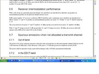
Thanks,vfone.I check it,but it is not in detail.It introduce simplely that receiver intermodulation,and i do not know which IM product i can get as following photo,can you help me?
Thanks
 

gfsk rf

Terry

ETSI cannot specify intermodulation products as they depends from your implementation. The system is interested in overall performance degradation, so BER.

If you want to measure internal system parameters (gain, noise, linearity) you should have a system partitioning study or specification that gives you the expected values so you can measure it.

It sound strange that you are designing something but you have measurement issues. Could you please explain more in detail it to better understand?

I hope it can help.

Mazz
 

    TerryADS

    Points: 2
    Helpful Answer Positive Rating
gfsk chip

You are not looking to the right spec.
The attached one probably is not the latest but it gives good explanation how to run this RF test (and others). Go to page 69.
 

    TerryADS

    Points: 2
    Helpful Answer Positive Rating
gfsk demodulation spectrum analyzer

Mazz said:
Terry

ETSI cannot specify intermodulation products as they depends from your implementation. The system is interested in overall performance degradation, so BER.
Can you explain in detail?
If you want to measure internal system parameters (gain, noise, linearity) you should have a system partitioning study or specification that gives you the expected values so you can measure it.

It sound strange that you are designing something but you have measurement issues. Could you please explain more in detail it to better understand?

Thank Mazz firstly.Because we want to evaluate the demo board,It is my first time design digital RF,i think it is different with FM system,and i need more informations about digital RF measurement firstly.especially IM product,linearity.
.in band and out band block.

I hope it can help.

Always thanks for your kindness
Mazz
Added after 24 minutes:

Also thanks vfone's kindness to me.
 

rf parameters for dect

Terry

Regarding the requested details, I will try to explain better with an example. Consider two differenr implementation of the DECT reveiver, the first one a superhet the second one a low IF.
In the first implementation you will have a first intermediate IF of about 110MHz and a SAW filter. In the second implementation you will have an IF of 1 MHz. For ETSI this is transparent.
Most probably you will have different gain in the two RX chains, different IM products and so on, but ETSI cannot take care about that.
It takes care of measurable end to end parameters do BER FER in RX.

Designing an RF system is the task to find the specification (such as gain, noise, Linearity...) of subblocks (from LNA, Mixer, Filter, VGA, demodulator and so on) in order to be compliant with ETSI end to end.

I hope it can help

Mazz
 
  • Like
Reactions: funfun

    TerryADS

    Points: 2
    Helpful Answer Positive Rating

    funfun

    Points: 2
    Helpful Answer Positive Rating
strange rf spectrum

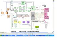
Thanks Mazz.Your explaination it is helpful,and i get it now.Attached the RF block we use,can you give me some suggestions what i can measure during estimating the RF chip?
Thanks
 

rf parameters you have measured

In this integrated solution, you have access only to antenna connector & TRDATA pin, so you can only measure end to end parameters, as specified in ETSI, to check if it is ETSI compliant.

Can you share with me the RF IC full datasheet?

Mazz
 

    TerryADS

    Points: 2
    Helpful Answer Positive Rating
Status
Not open for further replies.

Part and Inventory Search

Welcome to EDABoard.com

Sponsor

Back
Top