Continue to Site

Welcome to EDAboard.com

Welcome to our site! EDAboard.com is an international Electronics Discussion Forum focused on EDA software, circuits, schematics, books, theory, papers, asic, pld, 8051, DSP, Network, RF, Analog Design, PCB, Service Manuals... and a whole lot more! To participate you need to register. Registration is free. Click here to register now.

.TF equivalent in cadence...

Status
Not open for further replies.

bharatsmile2007

Full Member level 3
Joined
Sep 19, 2007
Messages
179
Helped
1
Reputation
2
Reaction score
1
Trophy points
1,298
Activity points
2,306
Hi All

In HSPICE .TF finds the ratio of small-signal input resistance to the small-signal output resistance.

How to find out the same through cadence?

Thanks
 

xf simulation
try: cdnshelp &
MMSIM 6.21
Products
spectre
Manuals, search for:
xf
7. Transfer Function Analysis (xf)

HTH! erikl
 

bharatsmile2007 said:
Hi All

In HSPICE .TF finds the ratio of small-signal input resistance to the small-signal output resistance.
How to find out the same through cadence?
Thanks
I am not familiar with HSPICE (but with many other simulation packages) - however, are you sure that .TF is really Rin/Rout ?? And what are you interested in ??
I suppose, .TF rather will be the small signal transfer function Vout/Vin.
 

Hi erikl and LvW

Thanks for ur reply's...

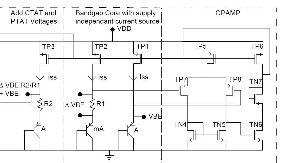
I wanted to find out the output impedance of BGR(Bandgap Reference Voltage) design.Can you pls let me know how to find the output impedance of BGR in cadence?

Pls find the schematic of BGR attached....

Thanks a ton... :)

76_1233318755.jpg
 

bharatsmile2007 said:
Hi erikl and LvW

Thanks for ur reply's...

I wanted to find out the output impedance of BGR(Bandgap Reference Voltage) design.Can you pls let me know how to find the output impedance of BGR in cadence?

Pls find the schematic of BGR attached....

Thanks a ton... :)

In each simulation program the output impedance of a circuit can be found by feeding a current (ac source) into the output and measure the voltage created across the output.
 
Hi LvW,

thanks for the reply...

I will connect a acm of 1Amp at the output node,perform ac simulation and find the voltage at the output node.so the Zout is the voltage at the node itself.

Am i correct? Pls correct if iam wrong....
 

bharatsmile2007 said:
I will connect a acm of 1Amp at the output node,perform ac simulation and find the voltage at the output node.so the Zout is the voltage at the node itself.

Am i correct? Pls correct if iam wrong....

Yes, this will work, too, (as in xf simulation), s. sim. plot below:
 
Thanks erikl..

Added after 5 hours 2 minutes:

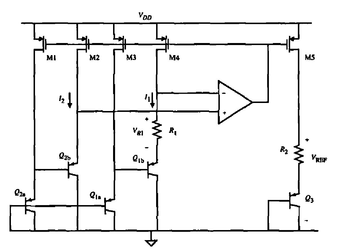
Hi,

Would you pls explain me the advantages and disadvantages of the below circuit?

Thanks

84_1233566786.jpg
 

Status
Not open for further replies.

Similar threads

Part and Inventory Search

Welcome to EDABoard.com

Sponsor

Back
Top