Continue to Site

Welcome to EDAboard.com

Welcome to our site! EDAboard.com is an international Electronics Discussion Forum focused on EDA software, circuits, schematics, books, theory, papers, asic, pld, 8051, DSP, Network, RF, Analog Design, PCB, Service Manuals... and a whole lot more! To participate you need to register. Registration is free. Click here to register now.

How to make a ideal ota(Gota, Rout) ?

Status
Not open for further replies.

twlin1

Member level 1
Joined
Nov 3, 2005
Messages
33
Helped
1
Reputation
2
Reaction score
0
Trophy points
1,286
Activity points
1,519
I just read paper "Design guidelines of CMOS class-AB output stages: a tutorial". In this paper, real output stage circuit and ideal first stage are combined to simulate.

My question is how to get the ideal OTA with two parameters: Gmota=100uuA/V and Rota=1M Ohm.

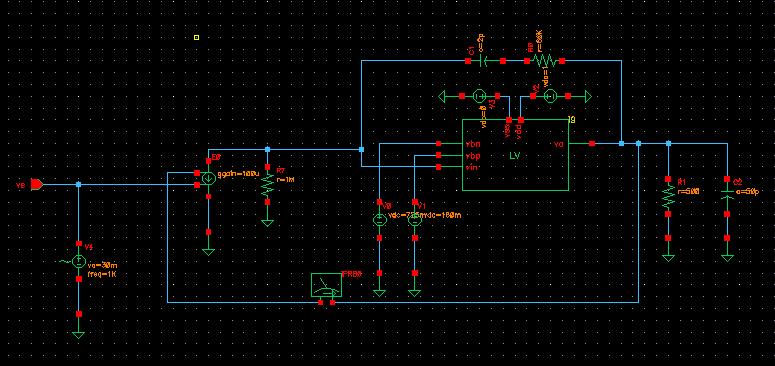
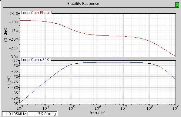
I have tried vccs(Gmota) with resistor(Rota). But I get wrong bode plot when doing stb analysis.

Can someone help me, thanks?


It seems that your ideal OTA is OK.

Perhaps the problem is not on your ideal OTA.

Real ideal OTA is only formed by E0. R7 is an extra load.
 

    twlin1

    Points: 2
    Helpful Answer Positive Rating
Dear angelote,

The first stage (ideal ota) I made with vccs and Rload has wrong stb result (no gain).

And if I replace ota with opamp (i.e., vcvs), it seems getting right dc operating point. But the bode plot still doesn't make snese.(phase margin <0)
But if I input sine wave and do transient simulation, "opamp (vcvs)+output stage" actually works with unit-gain feedback. And, the vcvs model can only represented by gain, not Gm and Rota.

So, what is the right behavioral ota model if given Gm and Rota ?

Thanks.
 

twlin1 said:
My question is how to get the ideal OTA with two parameters: Gmota=100uuA/V and Rota=1M Ohm.

I don't know much about your circuit, but I know that an OTA is a transconductance amplifier. It gives a current that depends on an input voltage (Iout=gm*Vin). This ideal behaviour is simulated using your E0(ggain).

The output voltage of an OTA depends on output load. If you use gm=100uA/V and an load of 1Mohm, the resulting voltage gain is 100. However, in your circuit, the OTA load isn't 1Mohm because it is in parallel to something else.

In OPAMPs, the first stage is an OTA, but you are trying to evaluate the output stage. I still think that the problem is not in the OTA implementation.

When you use E0(egain), R5 has no effect. Are you sure about that resistor?

I can't help you more that this becauso I don't know much about stability problems.

Good luck.
 

    twlin1

    Points: 2
    Helpful Answer Positive Rating
Status
Not open for further replies.

Part and Inventory Search

Welcome to EDABoard.com

Sponsor

Back
Top