Continue to Site

Welcome to EDAboard.com

Welcome to our site! EDAboard.com is an international Electronics Discussion Forum focused on EDA software, circuits, schematics, books, theory, papers, asic, pld, 8051, DSP, Network, RF, Analog Design, PCB, Service Manuals... and a whole lot more! To participate you need to register. Registration is free. Click here to register now.

What does it mean that IIP3 rating is -15 dBm?

Status
Not open for further replies.

robismyname

Full Member level 6
Joined
Jan 17, 2008
Messages
390
Helped
11
Reputation
22
Reaction score
9
Trophy points
1,298
Location
Central Florida
Activity points
4,603
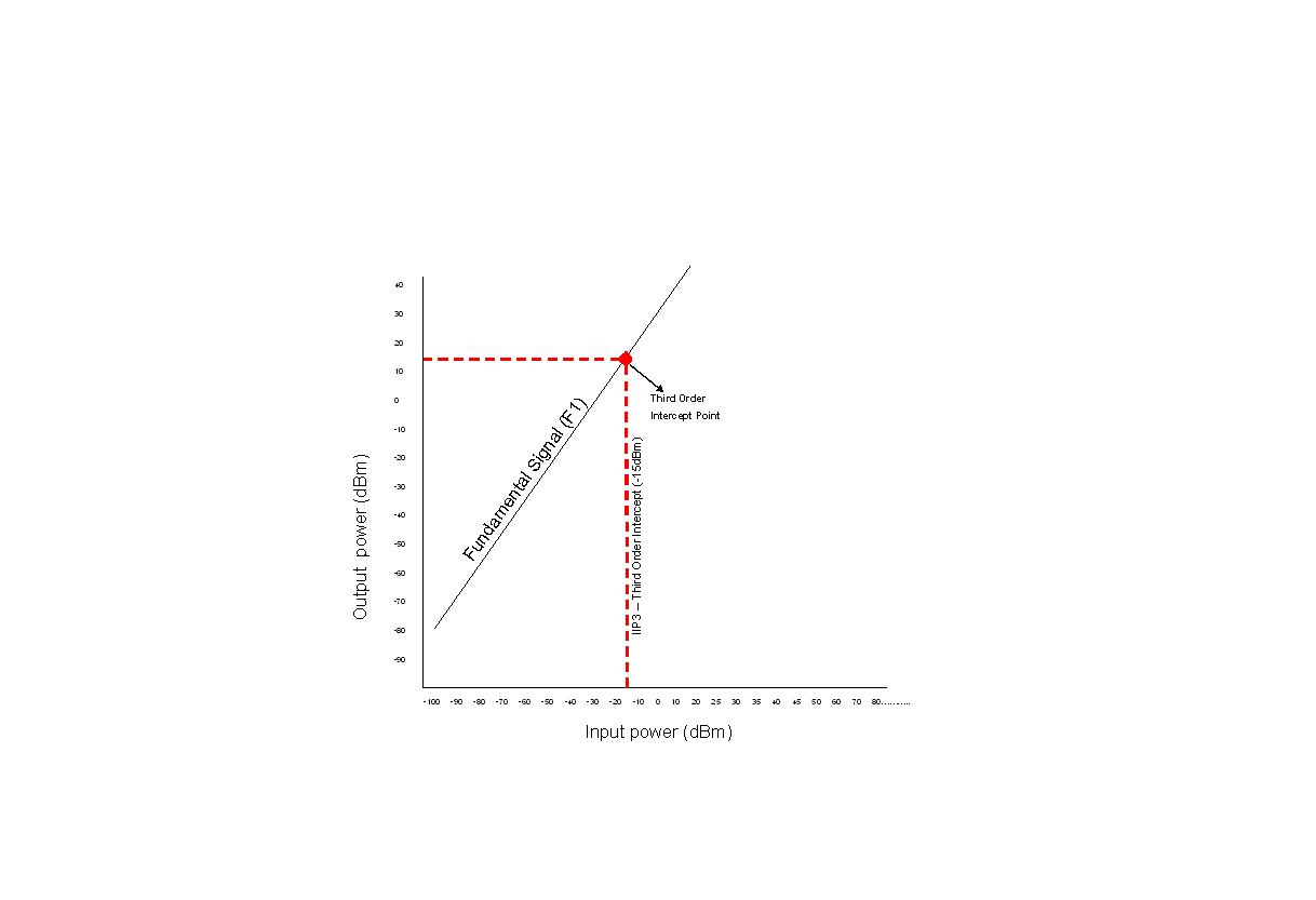
Having a time tough understanding IIP3 (Third Order Intercept Point). I am loking at a radio chip made by Serenza/RFMD that has a IIP3 rating of -15dBm. Does this mean that my input signal to the LNA will be equal to the intermod signal at -15dBm?
 

receiver iip3

No. IP3 is artificial point, actual signals do not go so far. You may use following rough estimation. Usually 1dB compression point is maximum input signal and it is roughly 10dB below IP3 point. Therefore, if you input IP3 (IIP3) is -15dBm, P1dB level will be about -25dBm. This means that your input signal range should be between this chip noise floor and -25dBm. But it is better to check P1dB point with datasheet.
 
iip3 formula

My IIP3 rating of -15dbm is an intersecting point, understanding that this intersection is an imaginary line, can you just tell me what:

1) What two lines are intersecting to make a intersecting point.
2) What is the smallest signal my LNA could receive with a IIP3 of -15dBm?
3) What is the largest signal my LNA can receive with a IIP3 of -15dBm?
 

cascading rf p1db formula

1. IP3 is the interception point between the first and the third order products lines. The first order line is the straight line which shows the relation between input and output signals plotted in dBm. This line crossing the vertical axis at the gain level in dB. The third order line is representing the third order product vs input level. This line has slope three times bigger than the first order. In real devices the first order line deviates from straight line starting from some input level and finally saturates (it is not always the true, but for the sake of simplicity let's consider this). There is the point where deviation of real line from the ideal is equal to 1dB. This point is called P1dB point and it is important parameter. Often this value is maximum working power level for the device. IP3 point usually (but not always) is about 10 dB higher than P1dB point.

2. I already mentioned that minimum signal is the noise floor and this level does not related to IP3. This is also not always the true, but for now we may do not touch this issue. You may consider noise floor as kTB+NF.

3. Maximum signal usually is equal to P1dB point except some special cases.
 
  • Like
Reactions: jlgr

    robismyname

    Points: 2
    Helpful Answer Positive Rating

    jlgr

    Points: 2
    Helpful Answer Positive Rating
oip3 iip3 and 1db compression point

How would derive the gain level of the first order line with a IIP3 of -15dBm? In this situation we are given the IIP3 but I am looking to draw the actual first order line. I assumed a RX sensitivity of -100dBm and a LNA with 20 db of gain. What did the vendor assume?

Would it be:

Input: -100dBm
Output: -80dBm
Input: -90dBm
Output:-70dBm

so and and so on up until you reach the Third Order Intercept Point? Please look at attachment, note I have not considered P1dB or saturation at this point yet.....


iip3的估算推导

Good point to check is Pin=0dBm, Pout must be 20dBm. For Pin=-15dBm Pout must be 5dBm. Please check it. Pin=0 dBm looks right but Pin=-15dBm looks to be higher.
 
catv level iip3

Ok I understand the transceivers IIP3 of -15dBm now however I noticed that the LNA that is being used with the transceiver has 20dB of gain and a P1dB of 22.5dBm. You already demonstrated that the transceiver's IIP3 of -15dBm equates to 5dBm OIP3 when the LNA gain is 20dB. You also demonstrated that the LNA should be used below compression/saturation/P1dB (about 3-10dB). So with a transceiver OIP3 of 5dBm and a LNA with a P1dB of 12.5dBm (22.5-10), do the parts work well together?

The LNA has an OIP3 of 36dBm, does this have any significant meaning in relation to the transceiver's IIP3 of -15dBm and a OIP3 of +5dBm?
 

p1db cascade

Now there is a mess. Before you talk about LNA parameters, but now you are talking about transceiver parameters. There is a big difference between these two things. We cannot talk about transceiver IP3 because there are at least two IP3s: one for TX part and one for RX part. You probably mean IP3 for LNA and for RX part of transceiver. In receivers noise figure often determined by the noise figure of LNA, but IP3 is almost never determined by LNA linearity. The last receiver’s cascade usually mostly determines the system IP3 value. If you want to determine the whole receiver’s IP3 you need to take reciprocal from the superposition of cascade’s IP3s with corrections for prestage gain. Here is the practical formula for n-stages receiver:

IP3rx=(1/((1/IP3a) +(Ga/IP3b)+(Ga*Gb/IP3c)+(Ga*Gb*Gc/IP3d)…+…(Ga*Gb*Gd….Gn-1/IP3n))

Here a, b, c d…n are receiver cascades, Gx –cascade gain and IP3x – cascade IP3. All numbers are linear, not in dB.

This formula assumes that there is no selectivity in receiver cascades, but this is almost always not true. To count the cascade selectivity you need to multiply each denominator when selectivity is found by the coefficient (Sx)^3/2. Here Sx is selectivity of cascade x for the frequency of interest.

You told that in your case LNA has 20dB gain and 22.5dBm P1dB point. I believe that it is output P1dB point, not the input. Otherwise output P1dB point must be 42.5dBm which is not real for LNA.
In this case input P1dB point for LNA is 22.5-20=2.5dBm and input IP3 is about 2.5+10=12.5dBm.
Then you have additional cascades with gain that reduce the system IP3 to -15dBm.

LNA with input P1dB =2.5dBm may have input level up to this point, sometimes less, sometimes slightly more. It is actually depends on system linearity requirements. For the sake of simplicity we, may consider P1dB point as maximum system input level = 2.5dBm. Then it is necessary to check all the chain for possible overloading. If its happen the input level must be reduced accordingly.

The minimum level as you pointed is about -100dBm. This is probably not low enough as we may expect for LNA with high gain. There is not so much sense to have 20 dB gain when input signal is actually not very low.

Next you gave one more number for LNA OIP3 as 36dBm. I want to have such LNA, but do not think it is real unless it is special multichannel CATV highly linear LNA with about 6dB noise figure and 150 mA current@5V.

In your post I found different numbers for LNA P1dB point. You confuse something. Probably you need to learn the basics of RF system budget calculations. It is also helpful to draw the block diagram and put the major numbers on it. In this case it is easy to see which parameter belongs to which part of the system and where are the total system parameters.
 
  • Like
Reactions: jlgr

    robismyname

    Points: 2
    Helpful Answer Positive Rating

    jlgr

    Points: 2
    Helpful Answer Positive Rating
Status
Not open for further replies.

Similar threads

Part and Inventory Search

Welcome to EDABoard.com

Sponsor

Back
Top