Continue to Site

Welcome to EDAboard.com

Welcome to our site! EDAboard.com is an international Electronics Discussion Forum focused on EDA software, circuits, schematics, books, theory, papers, asic, pld, 8051, DSP, Network, RF, Analog Design, PCB, Service Manuals... and a whole lot more! To participate you need to register. Registration is free. Click here to register now.

Simple debounce circuit for 89c51

Status
Not open for further replies.

srgrelic

Newbie level 5
Joined
Jul 9, 2008
Messages
8
Helped
0
Reputation
0
Reaction score
0
Trophy points
1,281
Activity points
1,370
max6816 arduino

Hey all,

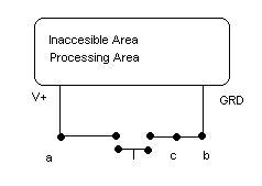
Can you suggest a circuit that could electrically sense when a button on a keyboard is activated and the circuit is closed (basically when a key is struck)?

The button itself must remain fully functional, and I could cut the trace on one side of the buttons contacts if the solution must be done in series, but if the solution could be done in parallel I'd be very interested in that idea.

This would be 100% DC, and I may even feed the results to a microcontroller.

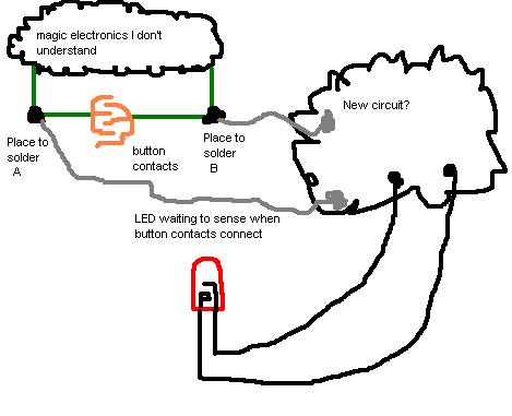
I can work that part out a little later, for now though, I'm stumped as to how I could "sense" a switch getting closed with components.

I've looked into optoisolators, but I fear that the voltage driving the led inside the optoisolator would be just enough to stop the keystroke from registering with the computer or whatever it's attached to.
 

Re: Simple sensing circuit?

Take a look:

**broken link removed**

hope it help.

Bye
powermos
 

    srgrelic

    Points: 2
    Helpful Answer Positive Rating
Re: Simple sensing circuit?

I'm not quite clear how debouncing circuits would help me with this problem.

Could you elaborate?
 

Re: Simple sensing circuit?

You can try to connect the input of the chip directly to the switch, into the datasheet some switch have a point to the 0 V (MAX6816) then if your key have a point to 0 V may be you can use this device to debounce and get the switch state change.
Anyway if you don't like to use such type of solutions there are other way, you can set up a differential amplifier with a comparator, make the value for the input resistor of the amplifier high enough to avoid any interference to the original circuit, when the differential voltage applied on the amplifier inputs became close to 0V or below some threshold you can suppose that the button was closed and take appropriate action.
Anyway could you post a simple draw of your circuit where you've to put the switch sensing?

Bye
Powermos
 

Re: Simple sensing circuit?

I'm including the simple circuit I'm trying to monitor.

The comparator and differential amplifier seem plausible. I do not know the voltage for this circuit at this time.

I've labelled 3 points on the circuit where I could solder. I would prefer A and B, since they are readily accessible, but I could also cut some traces on the PCB and sense between B and C if necessary.

Thanks for taking a look at this.

52_1215696810.jpg
 

Re: Simple sensing circuit?

If you've a point fixed to 0 V you can try to use a simple LM339 (open collector comparator) as a trigger.
You need to measure the voltage when the switch are open and set a treshold, e.g. a 1/2 of this value, to sense the switch closing. This a very simple approach, may be useful or not, just try.

Bye
Powermos
 

Re: Simple sensing circuit?

what is the voltage at point A? If it is 3.3 or greater then a simple logic gate will do fine.
 

    srgrelic

    Points: 2
    Helpful Answer Positive Rating
Re: Simple sensing circuit?

Ok, I'm trying to replicate this circuit's function in software, but cannot seem to get it to work. I'm posting a picture of what I've created. Can you help me fix it?


The LED and switch on the left side is the "load" that the switch drives and the switch I'm trying to monitor.

I don't think I'm fully grasping your schematic.
 

Re: Simple sensing circuit?

What is the voltage that you've set for the supply about the switch (on the left side in your schematic), if this is also 5V simply use for the resistor on the inverting pin two equal value like 4.7 k and 4.7 k, in this way the trigger will be on the half of the Vcc.
In your schematic the comparator output is fixed to 0V, leave it floating or simply put a 10k resistor between output and 0V rail, take in mind that LM339 is a open collector output then logic level 1 depend on the partition from pull-up and load, logic level 0 is near the 0 V due to saturation of a internal transistor.

Regard
Powermos
 

Re: Simple sensing circuit?

I dont know your voltage levels and what your intentions fully are but assuminig you just want an indicator when the switch is closed.

Just put a BJT NPN base at point C with base resistor,collector at point A,emmitter at ground. You can even put an LED for a visible indicator between the Vcc and collector with a current limit resistor.
 

    srgrelic

    Points: 2
    Helpful Answer Positive Rating
Re: Simple sensing circuit?

TekUT,

I'm still trying to work with your "Trigger" schematic but can't get it to work properly in software.

Max, Your assumption is correct, I simply want to be able to tell when a switch is closed. I will have an external power source, such as an arduino or something.

I tried your solution too, and I keep gettting the error message "Convergence failed".

97_1215804601.jpg


Could either one of you try this out on the software I'm messing with? It's a simple java applet to test circuits, if I can't get this working in theory first, I'm not comfortable getting these new components.

https://www.falstad.com/circuit/

Added after 8 minutes:

By the way, the top half of that circuit drawing I most recently posted is the "magic" portion of the circuit I'd like to "sense" the switch getting closed. I have no access to that area, nor do I want to alter any functionality of that area. The LED is only there to serve as a load for the switch to power when it gets closed.

The voltage will be variable coming from that "magic" top half of the diagram. I plan on using this circuit on many different devices ranging from keyboard buttons getting depressed, touch tone phone buttons, buttons inside a remote control...etc.
 

Re: Simple sensing circuit?

If you have nothing between A and B you need to limit the current with resistor R3. I'm assuming you have something there or else closing the switch would just be a short. Depending on what is there will determine what value for R3 or if its even necessary.

Spice doesn’t simulate a mechanical switch to well so I use a pulse source V1.

When the switch is open there will be zero volts at C the transistor is off, the voltage at the collector is the rail voltage. When the switch is depressed the voltage at C assuming nothing is between point A and the switch is the rail voltage. The transistor is on the collector voltage is Vce sat (small 0.3V). You can put an LED between the collector and the resistor if you want. You could also use a PNP depending on what signal you want for your output.

I haven’t spent time on resistor values you can figure them out.

You could use a BRT for the transistor and eliminate one resistor at the base. A BRT is a pre-biased transistor.

14mxafq.png


sooh38.png


    srgrelic

    Points: 2
    Helpful Answer Positive Rating
Re: Simple sensing circuit?

Ok, I just built the new circuit in the simulator app I'm using and once again the convergence failed. I don't understand why.

You mentioned something though, that made me question my description of the problem to the forum. You said, "If you have nothing between A and B you need to limit the current with resistor R3. I'm assuming you have something there or else closing the switch would just be a short."

I don't understand why that would be considered a short, it's closing the prebuilt circuit by the manufacturer of the device (keyboard, phone, anything with button contacts).

Will I need to cut the trace on the PCB and insert a resistor to prevent a short on the "monitoring circuit"? If so, would this resistor interfere with the normal operation of the switch I'm trying to monitor?

I appreciate your work in Splice plotting this out, but I'm also having a tough time deciphering where I would connect the circuit.

Here's a really bad MSPAINT image of what I can connect to:

88_1215811371.jpg


The LED is irrelavent but illustrates the point well, I'd like to light that led when the button contacts are connected.

In all honesty, if I could cut the trace and solder a relay in-line and the relay didn't resist any current, then that would work. Problem is, that trace wouldn't provide the voltage to drive the relay, and the resistance may mess with the electronics above the button.
 

Re: Simple sensing circuit?

You mentioned something though, that made me question my description of the problem to the forum.

To be honest, the description of the problem seems absolutely unclear.
 

Re: Simple sensing circuit?

Your diagram shows GRD (ground) at point C. If you close the switch you have a dead short from V+ to ground. That’s why I assumed you have something there, and you just omitted it in your drawing.

You should really know what’s in the “magic electronics I don’t understand” , before you start adding on components to perform a function.

You also never mentioned an additional circuit.

Don’t get upset but at this point the best suggestion I can offer you is to pick up a book and read it until you know what “magic electronics I don’t understand” is and what it’s doing. You can find several good books in the forum.
 

Re: Simple sensing circuit?

You first diagram shows C & B connected to ground. You show A as being positive. I assume that the following describes your circuit: You have a switch which goes to the input of a microcontroller or some other IC. This IC is pulling point A up to + via a resistor. When you close the switch point A goes to ground. To solve this problem you need to put a meter on A and measure the voltage when the switch is open. We will then know that the A switches beteen x volts and ground. If this voltage is 3.3 - 5 volts then I suggest that you take any logic IC, although a schmitt trigger logic IC would be recommended and use it to detect the switch closure. Fo example an inverter with an input atached to A will go HI when the switch is closed. If this is a schmitt trigger you could put a resistor between point A and input of the inverter and a small capacitor between the input and grnd. This will debounce your circuit. So the important thing here is to measure the voltage at point A with the switch open
 

Re: Simple sensing circuit?

All, thanks again for your help.

I think davidgrm explained my problem better than I did.

Right now this is only a theoretical circuit I'm working out, and I don't know it's exact application. Thus the lack of concrete details. You all are much more familiar with this than I am.

Instead of me trying to explain the the circuit, let me ask you all how you would accomplish the following (just in theory):

Joe Smith has a touch tone telephone with 12 buttons. He likes a visual representation of when the # key is pressed, and wants to light a small LED every time it gets pressed.

Joe doesn't understand the IC's inside the phone, and only has access to the button contacts for the # key on the PCB for soldering.

What kind of circuit can Joe build at the button contacts to light his LED and leave the phone's # key functioning normally?
 

Re: Simple sensing circuit?

srgrelic,
If the details of the phone are not known, it limits the range of possibilities.
Perhaps a simple circuit that relies on the current through the switch, rather than detecting the voltage, would be better. I have included a schematic as a general guide. General purpose PNP/Diodes will be ok.

When the phone switch is closed, current will flow through the diode, turning on the transistor, otherwise the diode is reverse biased and the transistor is off. This should limit the impact of the circuit upon the phone, and allow for a reasonable range of switch voltages.
 

    srgrelic

    Points: 2
    Helpful Answer Positive Rating
Re: Simple sensing circuit?

The touch-tone telephone example in fact helped me in understanding the problem.

To my opinion, it can and should be analyzed generally without considering
particular solutions cause it's a basic circuit problem. If you're clear about
the problem, you know which circuit can be used (if any).

I understand, that you try to monitor the switch state by measuring the voltage
differential at it's terminal. You don't know the monitoring method used by the
external "magic" circuit. Thus you are not allowed to inject a current iinto the
circuit cause it may disturb it's operation.

The only option to get information about the switch state would be to utilize the
unknown stimulus used by the external electronic. If the voltage differential at the
switch is non-zero, you can be sure that the switch is open. But you don't know the
waveform used by the external circuit to monitor the switch state, neither the
timing nor the current/voltage amplitude.

The touch-tone telephone e.g. is most likely using a switch matrix connected to a
logic-level circuit. In this case, you have a chance to get the required information.

But it may be even more complicated. If you have a membrane switch as used
with a computer keyboard, it won't show a clear open/short state rather than a
capacitance variation only. Your monitoring circuit has bad chances then.

My conclusion is in a short: Some knowledge about the external circuit is required,
your monitor circuit can't work unconditionally.
 

Re: Simple sensing circuit?

FvM is quite right, but it will always be necessary that some current flow in the switch, so it is a case of mimimising this current. Perhaps the base current of a BJT is too high, but an FET is a possibilty. It is likely that the array will be scanned, but unless this is very slow, the LED will appear to be continuously on.
 

Status
Not open for further replies.

Similar threads

Part and Inventory Search

Welcome to EDABoard.com

Sponsor

Back
Top