Continue to Site

Welcome to EDAboard.com

Welcome to our site! EDAboard.com is an international Electronics Discussion Forum focused on EDA software, circuits, schematics, books, theory, papers, asic, pld, 8051, DSP, Network, RF, Analog Design, PCB, Service Manuals... and a whole lot more! To participate you need to register. Registration is free. Click here to register now.

Measure high impedance signal

Status
Not open for further replies.

max0412

Full Member level 5
Joined
Oct 26, 2003
Messages
251
Helped
34
Reputation
66
Reaction score
5
Trophy points
1,298
Activity points
1,999
high impedance signal

I’m using a photo mosfet driver; to turn on a high side mosfet (M1).The driver is a Dual Photovoltaic LH1262CAC from Vishay. I can fully enhance a 16nC FET in about 700uS (13Vgs). The problem is I want to pulse the input to the driver and be able to monitor the Mosfet gate simultaneously. This way I can minimize current consumption. The second channel drives a small mosfet (M2) and is used for discharging the gate of M1 for fast turn-off (10 – 15 Us).The way I have it set up is that M1 gate capacitance can only discharge through M2 other then the leakage of M2 an nts4001 N-Fet which is negligible. See graph below.

NTS4001 LEAKAGE VERSUS TEMP and VDS

4v1ptu.png


I’m considering the AD8221 INAMP. Anyone have any suggestion on how to measure the output of the driver without loading it. I don’t have a $1000 FET differential probe obviously, or I wouldn’t be asking. The best I have is a 100x passive probe even this discharges the gate.

LH1262CAC datasheet

Code:
http://www.vishay.com/docs/83802/83802.pdf

AD8221 datasheet

Code:
http://www.analog.com/UploadedFiles/Data_Sheets/597695969332879224376031AD8221_a.pdf

Nts4001 datasheet

Code:
http://www.onsemi.com/pub/Collateral/NTS4001N-D.PDF

High side load switch FCD5N60 M1

Code:
http://www.fairchildsemi.com/ds/FC%2FFCD5N60.pdf
 

measuring high impedance

I don't understand how the AD8221 instrumentation amplifier can be a solution? If you intend to supply the OP from the driving side, what's the maximum voltage difference between circuit ground and output FET source. You're using a HV FET, I would expect several 100 V, far above AD8221 common mode range.
 

    max0412

    Points: 2
    Helpful Answer Positive Rating
general purpose high impedance amplifier circuits

FvM said:
You're using a HV FET, I would expect several 100 V, far above AD8221 common mode range.

Your right it’s for a 120-195VDC application. I’ve had it in the circuit for about a year. I’m just trying to reduce the current consumption. Right now it uses 15-17mA.

But you can use INAMPS beyond there CM range by using a precision resistive divider array (attenuate the input signal). Unfortunately this loads the signal depending on the divider R values. There are some difference amps with that high CM range but the input impedance is typically below 1Meg.

I have some DIP JFET opamp’s I’ll use one as a buffer, reference the mosfet source to a common ground and do that. I'd prefer to measure this in the actual circuit but...$ So I guess breadboarding it at 15VDC will have to do.

But if anyone has an inexpensive method for measuring small diff signals with high common mode voltages I’d be interested! A poor mans FET probe. The only way I can think is to use a precision R divider array and a Jfet INAMP. How does TEK do it?

Thanks for the reply
 

measuring high impedance

I understood, that you wanted to include the differential amp in the final circuit as a gate-voltage feedback. That's no completely impossible, but to my opinion, you reached the point where to consider an alternative gate-drive technique, e. q. using a transformer for energy transfer.

High voltage differential probes (apart from a special types with optical coupling and battery supply) are generally using compensated voltage dividers and FET fully differential amps. The circuit has several adjustments for common mode rejection and frequency compensation of the divider.

See a Testec 700V 20 MHz differential probe for reference
 

    max0412

    Points: 2
    Helpful Answer Positive Rating
measuring high impedance voltages

FvM said:
I understood, that you wanted to include the differential amp in the final circuit as a gate-voltage feedback. That's no completely impossible, but to my opinion, you reached the point where to consider an alternative gate-drive technique, e. q. using a transformer for energy transfer.

No using feedback would defeat the purpose of photovoltaic driver, simplicity. The mosfet it’s driving is a load switch on/off (SSR). I’m using this rather then a relay because of its low losses, and better reliability as well as a bit of experimentation.

To get the 700uS rise time I initially give the driver a 1mS 50mA current pulse, then constant current of 15mA. I replaced the typical resistor that’s used for discharging the FET with another FET the NTS4001 I mentioned earlier. The discharge resistor is typically 1-10MEG this resistor not only affects the discharge time (FET open) but also the charging (FET conducting) as well as the Vgs level. This gives me the full open circuit voltage of the driver and no current is diverted (wasted) through the discharge resistor, it also gives me a rapid turn off given the low Qg and Rdson of the NTS4001. Some fully integrated SSR do this as well it’ called dynamic discharge (optomoss if I remember correctly).These cost more and aren’t capable of handling more then 100’S of mA to maybe a bit over an amp.

I was looking for a way in which to measure the drivers output without loading it (discharging the FET through my probe).This would require an expensive FET probe like in your above post to do in the actual circuit. I’ll do what I mentioned earlier breadboard the driver and FET as a low side switch so I can see how long the mosfet gate remains charged with only the leakage of the NTS4001 to discharge it. I should be able to monitor the FET Vgs with a TL072 JFET opamp voltage follower. I think this whole switch can be made to run on uA's (mA pulsed low duty cycle average) rather then the 15mA it’s operating on now, after the initial 50mA pulse.
 

high impedance measure output voltage

If the purpose is to monitor Vgs just for development purposes, you might want to look into isolated amplifiers. They can float and transmit signal to level easily read by scope. You will need floating supply for amp conditioning and transmit circuitry capable of withstanding voltages invloved and high enough isolation so it does not effect your gate in any way. Medical grade dc/dc switcher should do a job.
 

    max0412

    Points: 2
    Helpful Answer Positive Rating
circuit design with ad8221

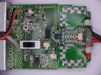
The testec differential probe isn't very expensive, it's basic function could be also achieved rather easily with a self-made circuit. But it's input resistance would be much to low for not affecting the gate circuit. I provided the photo cause you asked how they do. You can either use resistive dividers respectively resistive coupled differential amps with higher (e. g. 100 M) input resistance or true isolated amplifier, e. g. optical coupled, as suggested.

It may be a more simple option, to operate the switch with ground referenced source and floating drain for test purposes, provided that the common mode voltage doesn't change the driver operation considerably. As the required gate charge respectively ton depends on off-state Uds, the hightest operating voltage should be applied to the switch when determining ton. I see that you already considered this option.

Finally, if the switch circuit (apart from gate net) hasn't that high impedance, a buffer may also be supplied from current sources (respectively resistors) and Z-diodes. The buffer output can be coupled as current signal across the common mode voltage. This technique is often used for high side current sense circuits.
 

    max0412

    Points: 2
    Helpful Answer Positive Rating
high impedance analog buffer

FvM said:
As the required gate charge respectively ton depends on off-state Uds, the hightest operating voltage should be applied to the switch when determining ton.

Yes this was my concern and why ideally I would like to monitor Vgs in the actual circuit.I’ll use the jfet op amp monitor Vgs at on a breadboard in a lowside switch (source ground refrenced).Then put it in the circuit and monitor Vds and the FET temperature. Which is the best I can do without spending significant money or time.

FvM said:
he testec differential probe isn't very expensive,

Yes Newark has a testec ($49) in stock the input impedance is only 1MEG.Oddily enough even TEKS high-end HV probe only has 8MEG.This probe is pushing the 2 grand mark! Which is ridiculous for that amount of cash I would expect at least 1GIG.How these guys justify these prices for what is essentially a difference amp with a few other bells and whistles is beyond me?

The technology is there to make extremely high z differential probes. Ohmcraft makes precision resistor arrays well into the Gigohms.

Code:
http://www.ohmcraft.com/Resources/02_Data_Sheets/DS_HVD_HighVoltageLeadedResistorDividers.pdf

Extending the CM range of INAMPS using precision R arrays

m966vs.png


For anyone one else interested the above image was taken from the instrumentation Amplifier Handbook.

You can get it here.

Code:
http://artikel-software.com/file/instrumentation%20amplifier%20handbook.pdf
 

hi impedance circuit monitor

The problem is, that you need a compensated divider to achieve a higher bandwidth. It may be omitted if the amplifier has a suitable bandwidth limitation, e. g. 70 kHz with INA118 in the shown circuit.

Otherwise, the parallel capacitance of HV resistor would form a high pass that has to be compensated for. As it isn't actually a simple lumped capacitance, a dominant parallel capacitance is added usually.

When using multiple series connected resistors (5 x 1M MELF) for the divider, I found that a low pass with around 1 MHz cut-of is formed by the circuit capacitances, also without providing a compensation.

I have a principle schematic of the said Testec SI9001 frontend attached below.

You should consider, that these differential probes are mainly intended to measure higher voltages, they have some noise and offset, so for sensitive measurements, a true isolation amplifier would be the better alternative.
 

    max0412

    Points: 2
    Helpful Answer Positive Rating
isolated divider differential input

FvM & Sinisa


Do either of you know of an isolation amplifier similar to the AD202

Code:
http://www.analog.com/UploadedFiles/Data_Sheets/AD202_204.pdf

This looks like it would be perfect with the exception of the low input voltage spec +/-5V. Is there a way around this or another IA that can except differential voltages to 14-15V? In the same price range as the AD202 $50.00.

I see the AD210 fits the bill but at almost twice the price.

Code:
http://media.digikey.com/pdf/Data%20Sheets/Analog%20Devices%20PDFs/AD210.pdf

Thanks for the schematic!
 

what is impedance signal

You can use another low cost opamp with sufficient specs as a buffer for Vgs signal and feed it to resistor divider.

There are few kinds of iso amps arround, ones with magnetic and other with optical transmission. Optical ones seem to be cheaper with lower bandwidth.

Avago makes some nice opto's that you could use to build isolated amp. e.g HCNR200.
 

    max0412

    Points: 2
    Helpful Answer Positive Rating
high impedance switch

Sinisa said:
You can use another low cost opamp with sufficient specs ...

Yes that is the problem!

If you know of a high Z (Gohm) differential op amp with the following CM range let me know. I can’t find one which is the reason I started this thread. The differential opamp’s that I could find that have a CM range to the needed 200V have pathetic input impedance in the hundreds of k ohms, this is useless ; and can except differential inputs to 15V. Isolation isn’t necessary. Digikey has a few opamps that have CM range that exceed 200V but these cost more then an isolation amp.

This isn’t the first time I’ve had the need to make similar floating measurements. I guess I know what my next project is.
 

measuring high impedance signal

You can use another low cost opamp with sufficient specs as a buffer for Vgs signal and feed it to resistor divider.
I understand this as a suggestion to use either a floating or isolated supply for the buffer, otherwise the divider would make no sense. I recently also mentioned a solution with a floating supply:
Finally, if the switch circuit (apart from gate net) hasn't that high impedance, a buffer may also be supplied from current sources (respectively resistors) and Z-diodes. The buffer output can be coupled as current signal across the common mode voltage. This technique is often used for high side current sense circuits.
Both variants have restrictions and couldn't be regarded as general purpose differential probes. I can report, that most engineers in a lab are using resistive divider differential probes as the said Testec, Tek or similar with 5-10 Mohms input resistance for differential measurements, not only for power electronics, the intended main application.
 

    max0412

    Points: 2
    Helpful Answer Positive Rating
high voltage probe gohm fast

max0412 said:
This looks like it would be perfect with the exception of the low input voltage spec +/-5V. Is there a way around this or another IA that can except differential voltages to 14-15V? In the same price range as the AD202 $50.00.

I see the AD210 fits the bill but at almost twice the price.

My last post was in regards to this question. To extend range to desired 14-15V you can use buffer to maintain high Z and with divider bring it to ±5V for AD chip.
 

    max0412

    Points: 2
    Helpful Answer Positive Rating
differential amplifier floating signals

Bootstraping of regular opmap is another option, lower bandwidth though.

**broken link removed**
 

    max0412

    Points: 2
    Helpful Answer Positive Rating
Status
Not open for further replies.

Similar threads

Part and Inventory Search

Welcome to EDABoard.com

Sponsor

Back
Top