Continue to Site

Welcome to EDAboard.com

Welcome to our site! EDAboard.com is an international Electronics Discussion Forum focused on EDA software, circuits, schematics, books, theory, papers, asic, pld, 8051, DSP, Network, RF, Analog Design, PCB, Service Manuals... and a whole lot more! To participate you need to register. Registration is free. Click here to register now.

How to specify the Vcom voltage of sigma delta modulator

Status
Not open for further replies.
Hi jiangxb.

two questions:
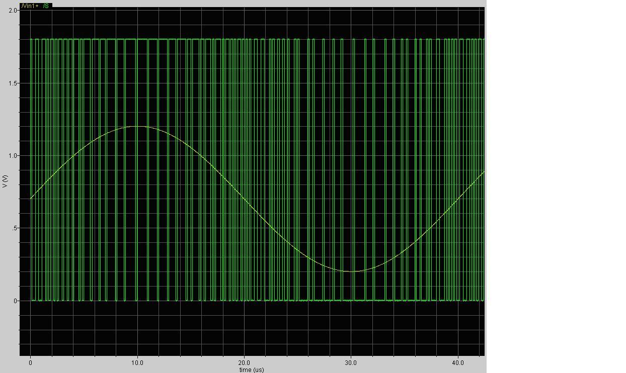
1) As i know, the integrator becomes staturated when the input signal is too large(I have tried the input with smaller amplitude, but made no difference). Does it related to the Vref?

2) can the vref- be below 0? must there be 1.4v difference between the Vref+ and Vref-?I know only a little to set the feedback voltage.Could give me some advice or some useful paper

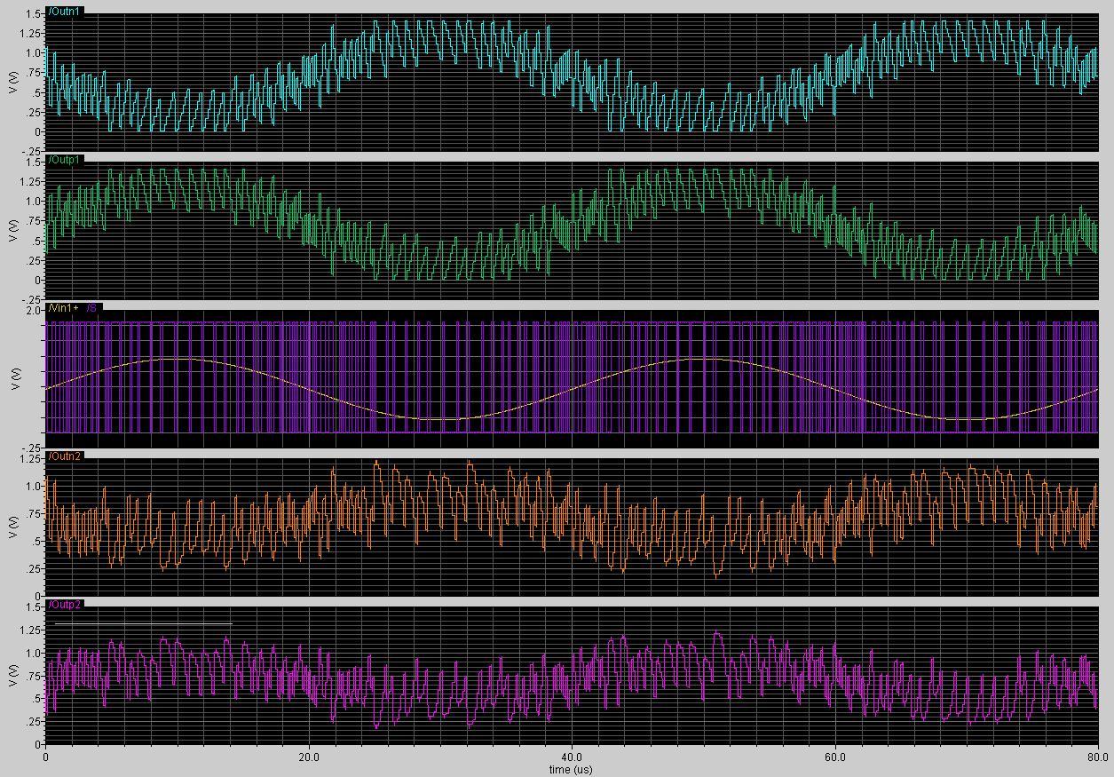
I will upload the simulation results soon!
 

hi BackerShu,

the output of the first integrator is g1*X*(1+1/z)/z-g1*E*(1-1/z)/z from your modulator, so g1, X and E influence the swing of the first integrator. E is quantization noise Δ²/12, Δ=2*(vrefp-vrefn). changing the difference between vrefp and vrefn influence the output swing.

if you use single power supply vref- can't be below 0.

in general i suggest system-level modelling modulator using simulink and set every parameter through simulation.
 

Hi jiangxb!

Than you very much for your explanation. In fact, I did some system level simulations before I come to the circuit implemention. At that time, I set the vrefp to Vdd, and vrefn to gnd without too much consideration.Obviously, I have to do many things to improve my work.

As for the circuit of 2rd modulator, I made a silly mistake that feedback Vref+ to the positve and negtive of the input at the same time.The value of Vref is all right,I think. Fig 1and2 shows the results that should be right.


Unfortunately, there is something wrong with the server in my lab that I can't upload the expanded figure to let you check if the result is really right. I will upload it later.

Thank you for your help all these days. If possible, could you tell me something that I should take special attention when I do the FFT analysis of the modulator's output. There is no one in my lab who has designed a sigma delta modulator before,and it's the first time I do this work. I can only refer to the books and papers.

Best wishes!
 

hi BackerShu, you have achieved excellent work, congratulation!
as for FFT you can refer to Richard Schreier's Understanding Delta-Sigma Data Converters, and i would like to help you if any trouble.
 

    BackerShu

    Points: 2
    Helpful Answer Positive Rating
Thank you for your recommendation. I will find and read the book carefully.
 

Hi BackerShu and jiangxb,
It is realy a good conversation.
I just want to ask BackerShu an explanation on the choice of the differential structure. Is it a general spécification for audio apllication or it has advantages vursus the simple one?
 

Hi joujou, sorry for late reply!
You mean to ask the advantages that the differential structure takes to the sigle-ended one.So far as I know, in designing the integrated circuit, the differential one is prefered, mainly because it depresses the even-order harmonic largely and has large ouput swing(ideally twice to the single-ended one) to get high SNR, especially in low voltage design. As to board level design, the single-ended structure is also used.
Hope this helps you!
 

Status
Not open for further replies.

Part and Inventory Search

Welcome to EDABoard.com

Sponsor

Back
Top