Continue to Site

Welcome to EDAboard.com

Welcome to our site! EDAboard.com is an international Electronics Discussion Forum focused on EDA software, circuits, schematics, books, theory, papers, asic, pld, 8051, DSP, Network, RF, Analog Design, PCB, Service Manuals... and a whole lot more! To participate you need to register. Registration is free. Click here to register now.

Feedback Resistor Values

Status
Not open for further replies.

jony130

Full Member level 3
Joined
Sep 6, 2006
Messages
168
Helped
51
Reputation
102
Reaction score
44
Trophy points
1,308
Activity points
2,326
Hi, how to determine correct values of feedback resistor in op-amp application :?:

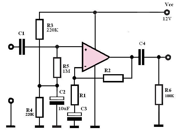
For example if we have to design non-inverting amplifier whit gain 11[V/V] and use uA741 op-amp KU=1+(R2/R1).
Whit of this values you will prefer and why :?:
option 1
R1=100Ω
R2=1KΩ

2
R1=1KΩ
R2=10KΩ

3
R1=100KΩ
R2=1MΩ
 

joni130,
You have not supplied enough information for a definite answer, so I will make the following assumptions:
.
1) The load resistance will be large (>10K)
2) You want to achieve an output swing of at least +/- 10V
3) The power suppy is +/- 15V
.
Unders these assumptions, I would pick the 1K, 10K combination. The 741 is only guaranteed to provide a +/- 10V output swing if the load is >= 2K. With the 100 Ohm, 1K combination the load would be 1.1K. With the 10K, 100K combination, the output error voltage due to offset current would be 10X higher than it would be for the 1K, 10K combo. Using the worst case value of 300nA for the 741C, the error would be 30 mV. If this is acceptable, then the 10K, 100K combo would also be OK. The output error due to input offset voltage is a function of the resistor ratio only, and not the values, so there is no advantage for any of the ratios given. Also, I'm assuming that the resistance from the NI input to ground would be equal to the parallel combo of the the input and feedback resistors, so the error due to bias current would be zero in all 3 cases
Regards,
Kral
 

    jony130

    Points: 2
    Helpful Answer Positive Rating
All values are "correct".
However, with respect to non-idealities of the opamp only one pair of values should be used: R1=1KΩ and R2=10KΩ

In general, the lowest resistor value should be much greater than the output resistor of the opamp (and, of course, greater than parasitic resistors of printed lines) and - at the same time - the highest resistor value should be much lower than the opamp input resistive impedance.

If possible, values R≥ 1MOhm should be avoided, since parasitic parallel capacitive effects degrade its performance already at relatively low frequencies.
 

    jony130

    Points: 2
    Helpful Answer Positive Rating
Thanks for answer.
So for AC-coupling, single supply amplifier, the load resistance 10K.
I could uses R1=1KΩ, R2=10KΩ or 10K; 100K or even 100K, 1M and nothing to worry about :?:
 

In a real application, you likely have additional requirements regarding bandwith, input impedance, noise, power consumption. Not all resistance values may be still acceptable then.
 

    jony130

    Points: 2
    Helpful Answer Positive Rating
So for AC-coupling, single supply amplifier, the load resistance 10K.
I could uses R1=1KΩ, R2=10KΩ or 10K; 100K or even 100K, 1M and nothing to worry about


You should use 10k/1k or 100k/10k or why not something beween (47k/4.7k) ?;
It really doesn´t matter - as long as resistors are in the low till medium range (e.g. no influence on bandwidth).

However, for single supply operation with capacitive coupling be aware of using a voltage divider in front of the non-inv. opamp terminal (for opamp biasing).
Because of power consumption as well as with respect to input impedance these two and equal resistors should be as high as possible (100k/100k).
 

    jony130

    Points: 2
    Helpful Answer Positive Rating
Ok. I understand, but I don't understand how this resistor can influence on bandwidth?.
For example this schema:

Lower cut-off frequencies is determine by.
Fd1=0.16/(C1*R5); Fd2=0.16/(R1*C3) and Fd3=0.16/(C4*RL).
Upper cut-off frequencies is equal:
Fg=GBP/Ku=1M/11=90KHz.
So I can choose R1 and R2 first and then calculated C3 to set bandwidth.
Is there any other factor that has effect on bandwidth that I don't mention.
And I suspect that noise is depend on Rin of amplifier :?:
 

I don´t see any errors. Looks good.
And you are right assuming that the values itself for R1 and R2 have no influence on BW (as long as R1*C3 remains fixed)
 

So in this specific example I could uses R1 and R2 from about 10KΩ to 1MΩ and nothing to worry about
 

Twice I have mentioned that - if possible - you should NOT use a resistor as high as 1MOhm.
 

    jony130

    Points: 2
    Helpful Answer Positive Rating
Ok thanks for help, and don't be angry.
 

No problem.
Good luck and big success.
 

The lousy old 741 opamp has an open loop voltage gain of about 11 at 90kHz. So the negative feedback from the resistors will reduce the gain. It would have a gain of 11 up to about 18kHz.
But its output slew rate limiting reduces its max output swing above only 9kHz.
 

Attachments

  • ua741_1780.png
    ua741_1780.png
    33.7 KB · Views: 164

    jony130

    Points: 2
    Helpful Answer Positive Rating
Audioguru said:
It would have a gain of 11 up to about 18kHz.
Can you tell me how you calculate this values.
Slew rate limiting for Ucc=12V (Vcc=±6V) gives Uomax=8Vpp (4Vp) so max output swing F=SR/2*pi*U=19KHz (I hope that this calculation a correct)
 

jony130 said:
Audioguru said:
It would have a gain of 11 up to about 18kHz.
Can you tell me how you calculate this values.
The graph shows a gain of about 11 at 90kHz. But I think that is the cutoff frequency where the gain is actually 3dB less. Then the negative feedback reduces the gain more. So the response is flat to only about 18kHz.

Slew rate limiting for Ucc=12V (Vcc=±6V) gives Uomax=8Vpp (4Vp) so max output swing F=SR/2*pi*U=19KHz (I hope that this calculation a correct)
You might be correct. Nobody knows becuse the lousy old 741 opamp is spec'd only for a 30V supply, not 12V. Many other opamps are spec'd at 30V and at 5V. The lousy old 741 opamp won't work properly with a supply of only 5V. Some of them might not work properly with a supply of only 12V.
 

    jony130

    Points: 2
    Helpful Answer Positive Rating
Audioguru said:
The graph shows a gain of about 11 at 90kHz. But I think that is the cutoff frequency where the gain is actually 3dB less. Then the negative feedback reduces the gain more. So the response is flat to only about 18kHz.
Yes, of course you're right. So it seems that I need to use some younger opamp.
 

Quote: The graph shows a gain of about 11 at 90kHz. But I think that is the cutoff frequency where the gain is actually 3dB less. Then the negative feedback reduces the gain more. So the response is flat to only about 18kHz.


No, that´s not correct.
The open loop response given in the data sheet shows the actual gain (not something like a 3-dB-limit), of course with some tolerances in the background.
Simulations confirm that a gain of 11 is flat until app. 80 kHz for the 741.

By the way: I´ve used the 741 app. in 50 different circuits - mostly with ±12 volts or ±15 volts and never have had any problems. But, of course, a "younger" opamp would be a good choice (because of slew rate limitations).
 

I was mainly surprized, that 741 is still used today, cause at the latest in the eighties we started to replace it by standard FET OPs (e.g. LF356) in all circuits with a certain bandwith requirement, used higher performance bipolar OP (e. g. OP07/27) for special applications or low performance LM324 for simple DC circuits.

Limitation by GBW should always be considered when designing OP circuits. Slewrate limitation may be a problem and it's good, that Audioguru mentioned it. It wouldn't matter for 100 mV only nominal output voltage, of course, but we don't know the specification.
 

The lousy old 741 opamp has high distortion at high audio frequencies. The frequencies of the fundamental and distortion harmonics all beat together and make a real mess of sound. There are certain pieces of music where you don't want the fuzz from a guitar effect.

Some people have damaged hearing where everything sounds like a telephone or like an AM radio. They are happy with a lousy old 741 or LM324 opamp. The LM358 and LM324 have bad crossover distortion in addition to slew rate limiting above a few khz.
 

I decided to use the TL072 or NE5532 It's easy to get those opamp in Poland and they are cheap to (2.2 euro for NE and 1.5 euro for TL).
 

Status
Not open for further replies.

Similar threads

Part and Inventory Search

Welcome to EDABoard.com

Sponsor

Back
Top