Continue to Site

Welcome to EDAboard.com

Welcome to our site! EDAboard.com is an international Electronics Discussion Forum focused on EDA software, circuits, schematics, books, theory, papers, asic, pld, 8051, DSP, Network, RF, Analog Design, PCB, Service Manuals... and a whole lot more! To participate you need to register. Registration is free. Click here to register now.

Please help with logic inverter

Status
Not open for further replies.

pn junctionitis

Newbie level 3
Joined
Mar 23, 2008
Messages
4
Helped
0
Reputation
0
Reaction score
0
Trophy points
1,281
Location
Texas. USA
Activity points
1,325
Rank amateur here. In fact this is my first attempt at constructing a useful electronic device, but there's something here that I just don't know about, and I can't figure it out.

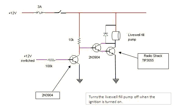
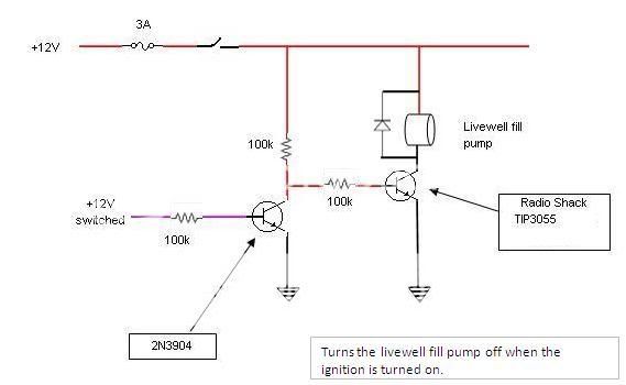
The application: my boat has a livewell fill pump which should be off while the boat is under way, but it's easy to forget to switch it off. So a circuit that simply disables the pump while the ignition is on, using a radio shack TIP3055 power transistor. It's a 12-volt system, meaning it needs to work at 12.6 to around 15 volts. The pump is on a 3 amp fuse, I expect it draws 1 to 1.5 amps during normal operation.

In my bench tests the voltage across the load with "ignition" switched off is a little over 4, enough to turn an LED on and off, but not enough to spin a small electic motor (225ma at 11.76 volts).

What am I missing here?

pumpcircuit.jpg


3055 datasheet
https://www.bourns.com/pdfs/tip3055.pdf

Thanks!!
 

The base current for 2N3055 is much too low. I would use a darlington circuit instead. But standard automotive or boating solution would be with a relays, I think.

59_1206297548.gif
 
Look at the datasheet for the 2N3055 transistor. Its max saturation voltage loss is 1.1V when its collecor current is 4A and its base current is 400mA.
Your max motor current is 3A so the 2N3055 needs a base current of 300mA.

You had a base current of only (12V - 0.7V)/200k= 60uA which was 5000 times too small.

The max allowed current for the little 2N3904 transistor is 200mA so it cannot be used to drive the 2N3055. Use a 2N4401 transistor instead which has a max allowed current of 600mA. Then it needs to have a base current of 30mA.
 

I have different data in 2N3055 datasheet, showing 150 mA base current at 4A collector current and 0.7V VCE . Furthermore, 1.5 A maximum continuous current had been said, so I think, for a hobbyist circuit, it should work so far. But it's not bad to use a transistor with higher current capacity. Basically, my approach was to suggest a working circuit instead of a surely inoperational circuit, using the available components.

On the other hand, for a professional design, your suggested component selection may be unsuitable as well, as it would no reliable withstand a blocked or shorted motor. As I said, a relay would be the usual solution.
 

Thanks all for the feedback.

I see that I completely failed to do the math.

I tried FvM's design 1st since it was easier to implement from what I had already done. When it didn't work (because I broke a pin, as I discovered later), I constructed Mr. rf's design using resistor values at the bottom of the recommended ranges, which I figure gives me base current of 44 ma and, according to mr.rf's formula (Ic = 50 * Ib), should yield a little better than 2 amps at the motor leads. It performed perfectly in bench tests using the same pump where it will be installed.

But, testing was done with no load on the motor. Which leaves me less than confident that it will work when I get it in the water; I'm a bit confused as to the base current requirement of the 3055......I have a recommendation of 30 ma, and one of 300 ma.

Thanks again,

[self-edit - simultaneous typing, FvM.......btw, good comment about blockages, I see now that the fuse will fail to protect this circuit. Will need to change to a 2-amp fuse. p.s., you're right about the use of relays in marine applications, I'm just determined to find cheaper DIY applications where possible without compromising safety]
 

Let’s try the opposite way… :D
A fuse of 3 Amps impose a maximum current of 2Amps. Instead of two amps let’s try checking at only one amp. If it’s only 1Amp a 2N3055 for 15mA base current will saturate at 0.5V, for 30mA will have 0.2V Uce.
What about increase to1.5A? For 30mA we have a maximum 0.8V Uce…

Is there any compromise between those two situations? :lol:
I know a 2N3055 is a lousy transistor at high currents, but will do the work for only 1 or 2 Amp.
My 2 cents.
8)
 

FvM said:
I have different data in 2N3055 datasheet, showing 150 mA base current at 4A collector current and 0.7V VCE.
You are talking about a typical 2N3055 transistor. You can't buy one. You might order 100 and they all might have minimum gain. You get what they have. Maybe they sold all their "good" ones before you ordered a transistor.

I always design circuits that always work even if the parts are minimum but are still guaranteed.
 

I always design circuits that always work even if the parts are minimum but are still guaranteed.
Two comments: 1. As I said, it wouldn't help you in this application. 2.I'll check occasionally with your circuit designs, I always do is a strong statement.
 

Why not use a resistor to give enough base current so that all 2N3055 transistors will work in the circuit, instead of only the typical and better ones?

This circuit does not need to minimize current drain.
Your proposed circuit with low base current will fail early if the transistor has low (but still passing) gain and the motor draws more current than planned.
 

Status
Not open for further replies.

Part and Inventory Search

Welcome to EDABoard.com

Sponsor

Back
Top