Continue to Site

Welcome to EDAboard.com

Welcome to our site! EDAboard.com is an international Electronics Discussion Forum focused on EDA software, circuits, schematics, books, theory, papers, asic, pld, 8051, DSP, Network, RF, Analog Design, PCB, Service Manuals... and a whole lot more! To participate you need to register. Registration is free. Click here to register now.

Coaxial fed patch antenna HFSS11

Status
Not open for further replies.

Rerodz

Junior Member level 1
Joined
Feb 23, 2008
Messages
15
Helped
1
Reputation
2
Reaction score
1
Trophy points
1,283
Activity points
1,367
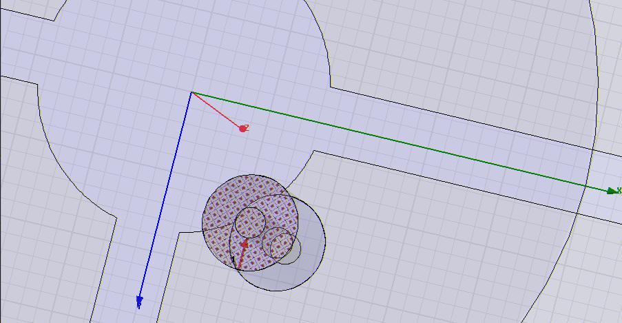
coax fed patch antenna design

This is my first time using HFSS. I've already made the 3d model but not sure how to set the center core of the coaxial as a terminal port.

Suggestions?
 

waveport excitation+hfss11

i am using hfss 9 and this might be a lot similar to 11.

first make a circle that covers the coax input. i usually set this to be somewhat transparent as i find it easier to see the line i defined for my waveport later on. please make sure that your solution is in driven terminal as well.

after making the circle, right click on it, assign excitation, click on wave port. click next once. then on the drop down menu, define a new line. draw the line such that you start at the outer conductor (ground of coax) and only up to the radius of your inner conductor (+). if your line is invalid, hfss will prompt you to draw the line again. please see picture attached.

then click next once the line you drew is valid. Z0 is 50 ohms by default, change it i guess if you wish. then you're done..

hope that helped.

 
coaxial fed patch antenna

Thanks I'll try that. : )
 

coaxial dimension

hi Rerodz...
u can refer user guide hfss...there have complete description...


regards

alan
 

hfss11, antenna design

Thanks guys. I got it now. :) I'll let you guys know how it turns out. Eventually I'm going to put a "U" shape slot in the center hoping to increase the bandwidth.
 

I'm having trouble again..

Everything is validating and running well but not so good results. Can someone take a look at it.

See attachments..
One is on Duroid6010 and the other on Duroid5880

Please help
 
What do you mean by no so good results? Would you please let us know your requirements!

However, there are two things which may be wrong. First of all, you didn't define any radiation boundary. You drew a box (non-metal!!), however, forgot to define it as radiation boundary. Better use airbox (vaccum) and define the boundary. Secondly, you coax inner and outer dimension donot give you 50 ohm impedance (inner R = 0.9 mm, outer R = 2.9 mm) @ 2 GHz, rather it give around 70 ohm. (please check it!). May be you wanted 70 ohm?

Please take a look at the attached file (updated) and return loss curve.


Regards,
Shameem
 

Thanks for replying

I've set the box to Rad1 and changed the coax to .7 mm for core and 1.6 mm for the dielectric but the results are still ugly.

I've posted a new file with changes
 

Hi!

You forgot to put metal outside of your coaxial. I extended the ground plane until your coaxial which serves as outer metal for coaxial. Take a look at the file.

What is your requirement for this antenna? Are you following any paper for this?

Regards,
Shameem
 

I'm trying to make it work at 3Ghz then I'm making a slot around the center in the shape of a "U". The slot is should help the bandwidth. I read about it on an IEEE paper.

It's called " Single-layer single-patch wideband microstrip antenna" by T.Huynh and K.-F. Lee

They claim the the slot improve the bandwidth by 10-20%
 

would you please upload the paper ("Single-layer single-patch wideband microstrip antenna" by T.Huynh and K.-F. Lee)! I don't have access to electronics letters.
 

Shameem
I was looking at the file where you fixed the coax outer metal. What is that line you drew at the center of the core?
 

Hi!

while setting up the waveport you can define the terminal line. This line refers to the electric field in this case.

Regards,
Shameem
 

Here is the document ..
 

Dear Rerodz,

Why don't you first design the same patch as the paper which is designed for 900 MHz? If you can reproduce the result as the paper, then it is easier to switch to your design frequency.

regards,
Shameem
 

hey man if you r done with your exact design then can you please upload your design....i am also working over the same thing...so i need to look at your design.....as i tooo aint getting the same results
 

I would like to ask a question. How do you choose the radius of probe inner/ outer?
I see for big patches (cm dimensions) 0.7/1.6 mm but what about small antenna patches in mm dimensions? It is too big for them.
 

Does anybody see a patch like Rerodz post, but circular polarized in wide band? I need VSWR 2:1 and AR=3dB band over 3-4%... Thank you!
 

Status
Not open for further replies.

Part and Inventory Search

Welcome to EDABoard.com

Sponsor

Back
Top