Continue to Site

Welcome to EDAboard.com

Welcome to our site! EDAboard.com is an international Electronics Discussion Forum focused on EDA software, circuits, schematics, books, theory, papers, asic, pld, 8051, DSP, Network, RF, Analog Design, PCB, Service Manuals... and a whole lot more! To participate you need to register. Registration is free. Click here to register now.

Simple Fm transmitter

Can Jokker make it work OK ?

  • Nah ... Its too plain construction.

    Votes: 0 0.0%
  • Depends on components he uses.

    Votes: 0 0.0%
  • There is something "Jokker" dont know :)

    Votes: 0 0.0%

  • Total voters
    0
Status
Not open for further replies.

JoKKeR

Full Member level 2
Joined
Feb 14, 2008
Messages
130
Helped
2
Reputation
4
Reaction score
2
Trophy points
1,298
Location
Estonia
Activity points
2,281
simple fm transmitter

Hi !

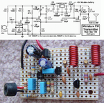
Lately iv made a very simple FM transmitter.

fmtrans2.gif


More info:


So the reson i made this post is that its working badly.
As u see there are 2 inductors and i made them by using wire, so i m pretty sure that the reason why its not working clearly is these inductors (mutaded voice, much noise)

And Yea i no that i cant run in next to radio coz there are effect named "resonance"

So can someone advise me something(how to make it work better) and how i can make variable inductors by my own using plain materials (My bet is that ill cut little plastic tube from a pen and pun inside it something ... anything metal ?)


And if u want badly i can take a pic of it.


Thank you !
 

simplest fm transmitter

The simple FM transmitter circuit is a child's toy.
Its antenna connects directly to the tuned circuit so its frequency changes all over the place when something gets near it or moves away.
It doesn't have a voltage regulator so its frequency changes as its battery voltage runs down.
It doesn't have a supply bypass capacitor like most circuits on that site so it might not even work like most circuits on that site.
It doesn't have pre-emphasis (treble boost) like FM and TV stations so it will sound muffled on an FM radio like your stereo with its treble tone control turned all the way down.

Somebody complained on another site that a circuit like that didn't work. I explained why it didn't work then made it to see if I am correct. It didn't work.
So I improved it and now it works perfectly.

I added an RF amplifier, a low dropout voltage regulator and pre-emphasis.
 

Attachments

  • fm_transmitter_pic___schem_4018.png
    fm_transmitter_pic___schem_4018.png
    195.9 KB · Views: 488

    JoKKeR

    Points: 2
    Helpful Answer Positive Rating
simple fm transmitter circuit

What Audioguru gave is enough. I would like to add that do not used any metal or any other material (unless it is required or told you to do so) inside the inductor (only for winding purposes then remove it). Because it will change the inductance drastically, so the carrier. and if you are using a wire that have no insulation or enamelled, then make sure turns do not touch each other, and by the way you have to wind an inductor having low inductance, for that turns should be spaced. You can change frequency by giving more space or less between the turns.
 

    JoKKeR

    Points: 2
    Helpful Answer Positive Rating
how to make a simple fm transmitter

Another Simplest Fm Tx.
I used it withonly 5cm naked wire as antenna and it woks!CIRCUIT DIAGRAM
PARTS LIST
R1, R3 = 100K
R2 = 10K
R4 = 470 ohm
C1, C4 = 470pF
C2, C3 = 4.7µF, 16V, electrolytic
C5, C6 = 4.7pF
C7 = 4-40pF trimmer cap (optional)
L1 = 1µH
Q1, Q2 = 2N2222, NPN transistor
Mic = Electret Microphone
B1 = 9 Volt, Alkaline battery
[/u]
 

a simple fm transmitter

As a remark. None of the displayed circuits is actually a FM transmitter, they all are AM transmitters producing some parasitic FM. That may be one reason for poor quality. A real FM transmitter would have a varactor diode as modulator and possibly additional measures to reduce AM.
 

    JoKKeR

    Points: 2
    Helpful Answer Positive Rating
fm transmitter 2n2222

Thank you for ur replies .. and u helped me very much ...

And yep there are this effect that i ill chane position of transmitter im losing signal ... and there is one thing more ...

If im using variable capacitor ... im turning it with knife so im getting whistlering (annoing noise ) So far as i no it should be like that .. coz im acting very next to radio , but bad side is that if im taking this knife off then im starting to get same poor noise. I tried to increase distance between radio and transmitter ... max when i heard something was 10 m, But i remember that 2 years ago its when i made it worked pretty good ( very low noise )
 

little fm radio transmitter making

The oscillator transistor in a simple FM transmitter is the varactor diode. The collector-emitter capacitance changes with the modulation so it produces high quality FM. It also produces a little AM but FM radios ignore the AM.

I tune the tiny trimmer capacitors of my FM transmitter with a plastic screwdriver that does not affect the capacitance when it touches.

If the transmitter is near a radio then of course you will have acoustic feedback howling. Turn down the volume or separate them.

My FM transmitter overloads the untuned input of my cheap Sony Walkman and clock radios so that the signal appears at many spots across the dial. Then it is impossible to tune the transmitter properly. Luckily my home stereo tuner does not overload and my Sony Walkman has a 'local-distant" attenuator switch.
 

simple transmitter

adeel.sid said:
Another Simplest Fm Tx.
I used it withonly 5cm naked wire as antenna and it woks!CIRCUIT DIAGRAM
PARTS LIST
R1, R3 = 100K
R2 = 10K
R4 = 470 ohm
C1, C4 = 470pF
C2, C3 = 4.7µF, 16V, electrolytic
C5, C6 = 4.7pF
C7 = 4-40pF trimmer cap (optional)
L1 = 1µH
Q1, Q2 = 2N2222, NPN transistor
Mic = Electret Microphone
B1 = 9 Volt, Alkaline battery
[/u]

hi Adeel.sid
now in my labratory i should use the same circuit that u showed, can you please show me the output waveform in spice or othere softwares?

i will be very thankful of you...
 

materials used in simple fm transmitter

I did it very long time ago.
I do not have any spice simulation for this circuit.
 

simple fm transmetter circuit

As a remark. None of the displayed circuits is actually a FM transmitter, they all are AM transmitters producing some parasitic FM. That may be one reason for poor quality. A real FM transmitter would have a varactor diode as modulator and possibly additional measures to reduce AM.
-------------------------------------------------------------
I'm disapointed with your knowlege FvM?????
-------------------------------------------------------------
Audioguru is give right explainatioin.
5 STARS this time for AUDIOGURU !!!!!!![/quote]
 

Status
Not open for further replies.

Part and Inventory Search

Welcome to EDABoard.com

Sponsor

Back
Top