Continue to Site

Welcome to EDAboard.com

Welcome to our site! EDAboard.com is an international Electronics Discussion Forum focused on EDA software, circuits, schematics, books, theory, papers, asic, pld, 8051, DSP, Network, RF, Analog Design, PCB, Service Manuals... and a whole lot more! To participate you need to register. Registration is free. Click here to register now.

change led driver from 5mm to 10mm LED

Status
Not open for further replies.

pasicr

Advanced Member level 1
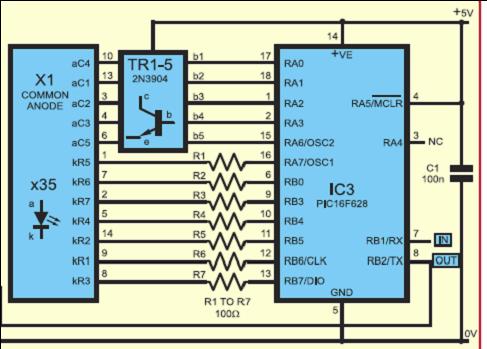
Joined
Aug 13, 2005
Messages
440
Helped
39
Reputation
80
Reaction score
29
Trophy points
1,308
Location
Macedonia
Activity points
4,213
10mm red led drive

Hi for all,
I use led driver (picture 1)
32_1201732378.jpg

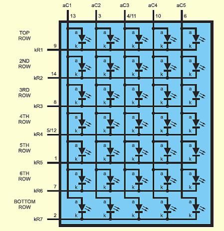
for drive led matrix 5x7 (one led is 5mm, picture 2).
16_1201732409.jpg

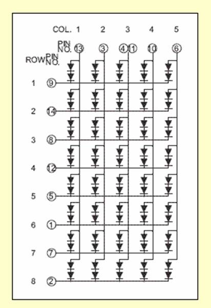
Now I buy led matrix but larger with 2x5mm led (5x7, picture 3).
98_1201732455.jpg

With old led driver, new led display with 10mm led give weak brightness,
I like to hear opinion from everibody, how to change old led driver, with minimum modification, to get maximum from new led matrix,
(for example increase voltage on chatode on 2N3904?...),
regards
p.s. new led display is 5x8, is not a problem, I not use bottom row
 

10 mmm led driver

Hi Pasicr,

You actually did it the wrong way, you should have used 2N3906's to
drive the anodes of the leds. You can change it but you gonna have
to connect the emitters of the 2N3906's to the five volt supply and
the collectors to the anodes of the leds AND add five base resistors
to limit the base current. Don't forget to invert the outputs RA0 to RA6.
If you already have a pcb you don't have room for the base resistors.
In this case you substitute the 2N3904 transistors with P-channel fets,
the sources are connected to the five volt supply, the drains go to
the anodes of the led matrix and the gates go directly to the outputs
of the pic and you also invert the drive of the outputs of the pic.

on1aag.
 

2n3906 led driver

Reduce the 100 Ohm resistors to increase brightness. Don't reduce the resistors too much or you will burn out the LEDs. Keep current on each LED below Imax - usually around 10mA or so is safe, 20mA is pushing it close.

Added after 11 minutes:

Hi On1aag,

I agree it's not the most effective way to drive the matrix, but I think it might be still salvageable. Assuming base is at +5V, Vbe = .7V, + (2*1.9V Vfwd - I'm assuming red LED, you don't have a chance if it's blue or white LED) = 4.5V. As long as the 100 ohm resistors are small enough (50 ohms or so) the LEDs should turn on.
 

led 5x7 matrix driver pcb india

Drive the Display directly from the PIC outputs with no limiting resistors and no BJT or FET. PIC FET outputs are source self-limiting at 25ma. Connect the 8 Sink lines directly to PIC outputs also.

For such a simple single LED Matrix circuit.... throw all the other components away!

I have proven this setup with several demonstrations on YouTube. Here are the
connections I used with an 8x8 LED Matrix:
**broken link removed**

Here is a 2-Color LED test with no limiting resistors while connected directly to a PIC. The bi-directional LED is plugged directly into a socket on the board. The meter shows the current in each direction:

Here is a series of 8x8 Matrix videos with the Matrix LED's connected directly to a PIC without limiting resistors or transistors (I have many more video demos if you look for "circuited" http://www.youtube.com/profile_videos?user=circuited):


    pasicr

    Points: 2
    Helpful Answer Positive Rating
what is the different 5mm led and 10mm led ?

Those are cool videos, nice work. One day I'll finish my LED sign kit.
 

5mm & 10mm led

Hi Xorcise,
I will try,
this is a very good video material,
congratulation,
best regards
p.s. You use 18F452, this is a new series of PIC micro, have it a same output capability with 16F628?
 

The electrical specs for PIC IO is not so different actually. And, you will not exceed the total PIC package power by driving the display at full IO current. A 16F628A will work fine for your project. Try it.... you'll wonder how it was so easy.

For a 5x7 display, source 5 lines and sink 7/8 lines as needed.... 12 IO total. For best even brightness, scan the sink side and drive data on the source side. The current on a sink IO pin can get a little high in this configuration since you are dumping up to 5 sources running at 25ma. But you have to remember that you have a duty cycle of 12.5% and are not going to cause any damage. Otherwise, you can reverse the process by scanning the source side and driving all the sinks with the data to be displayed. In that case you will never exceed the normal (very safe) limits of the IO.

The latter configuration (driving data on the sink lines) requires the least of amount of PIC memory to store font tables. You only need 5 bytes per character. The first configuration requires 8 bytes per character.

You will find PIC's almost indestructable. They have a lot of protection limits, both inherent and built-in.
 

    pasicr

    Points: 2
    Helpful Answer Positive Rating
xorcise said:
Drive the Display directly from the PIC outputs with no limiting resistors and no BJT or FET. PIC FET outputs are source self-limiting at 25ma. Connect the 8 Sink lines directly to PIC outputs also.

For such a simple single LED Matrix circuit.... throw all the other components away!

I have proven this setup with several demonstrations on YouTube. Here are the
connections I used with an 8x8 LED Matrix:...


xorcise said:
The electrical specs for PIC IO is not so different actually. And, you will not exceed the total PIC package power by driving the display at full IO current. A 16F628A will work fine for your project. Try it.... you'll wonder how it was so easy.

For a 5x7 display, source 5 lines and sink 7/8 lines as needed.... 12 IO total. For best even brightness, scan the sink side and drive data on the source side. The current on a sink IO pin can get a little high in this configuration since you are dumping up to 5 sources running at 25ma. But you have to remember that you have a duty cycle of 12.5% and are not going to cause any damage. Otherwise, you can reverse the process by scanning the source side and driving all the sinks with the data to be displayed. In that case you will never exceed the normal (very safe) limits of the IO.

The latter configuration (driving data on the sink lines) requires the least of amount of PIC memory to store font tables. You only need 5 bytes per character. The first configuration requires 8 bytes per character.

You will find PIC's almost indestructable. They have a lot of protection limits, both inherent and built-in.


For the 628A:

"Maximum output current sunk by any I/O pin..........................................................................................................25 mA
Maximum output current sourced by any I/O pin ....................................................................................................25 mA"

Note that if you set an output low and meter it to the 5V rail, most midrange PICs will do 35 mA, and set high to the low rail will give more like 30 mA. Note both of these are above the max allowable, you're still technically required to limit current to be within specs. I do it all the time myself as well, but you must be aware of the risks. Only thing limiting it to even that is the channel dimensions of the output FETs, and that isn't a guaranteed spec, could get a different PIC tomorrow that sank 2A on an output.. :) Not likely though, it would upset the apple cart.. Older PICs would do 100 mA on an output, but those aren't common now.

Tons of info on the internet says it like that, but it's wrong, just because the PIC doesn't destroy itself on a short people assume it is self limiting. Simple to set a pin low and check to 5V etc and see that while it doesn't destroy the pin it certainly exceeds the spec. Technically you are running the risk of that and/or latchup or really any other possible problem, but I haven't ever had a problem that I'd attribute to it either..

You won't ever get more than that 35 mA into a pin. Won't matter if you have all 7 on and they would each do 30 mA into ground, using one pin as a sink you'll never get more than the 35 mA it would pass from +V into ground. Since the high side channel resistances will balance the LEDs, 7 on should get full duty for their pin cycle, while down to 1 on should get about 1/7th of it's full duty. But modern LEDs are so bright that it's hard to notice optically for most things, I rarely bother with this for things I direct drive.


And while it won't with just a single scanning item like this, for the newbies it is good to point out that if you get using this a lot (pins to run things with no resistors), it's easy to exceed port or package specs if you start having a lot of things that can all be 'on' at once. Basically you can short everything to hell and they'll stay working, but you're also far outside any notion of guaranteed operation.


Works, use it tons myself. But for sure you are taking all possible problems on yourself any time you use this, the reason it limits to 35 mA isn't a guaranteed spec but is determined by process dimensions, and even that is over what specs say you're ever supposed to allow on a pin. Works great, but if it FUBARs you are just a loser, so you have to keep it in mind.. :)
 

Reduce the resistor value to 75 ohms instead of 100 ohms
 

Status
Not open for further replies.

Part and Inventory Search

Welcome to EDABoard.com

Sponsor

Back
Top