Continue to Site

Welcome to EDAboard.com

Welcome to our site! EDAboard.com is an international Electronics Discussion Forum focused on EDA software, circuits, schematics, books, theory, papers, asic, pld, 8051, DSP, Network, RF, Analog Design, PCB, Service Manuals... and a whole lot more! To participate you need to register. Registration is free. Click here to register now.

Problem with PWM signal which is fed to KB817 optocoupler

Status
Not open for further replies.

ScratchBuild

Member level 2
Joined
Nov 8, 2006
Messages
51
Helped
2
Reputation
4
Reaction score
0
Trophy points
1,286
Location
South Africa
Activity points
1,705
Hi there,

Can you please help me. I am not at all a professional in electronics and have a problem I am sure you have a quick answer too.

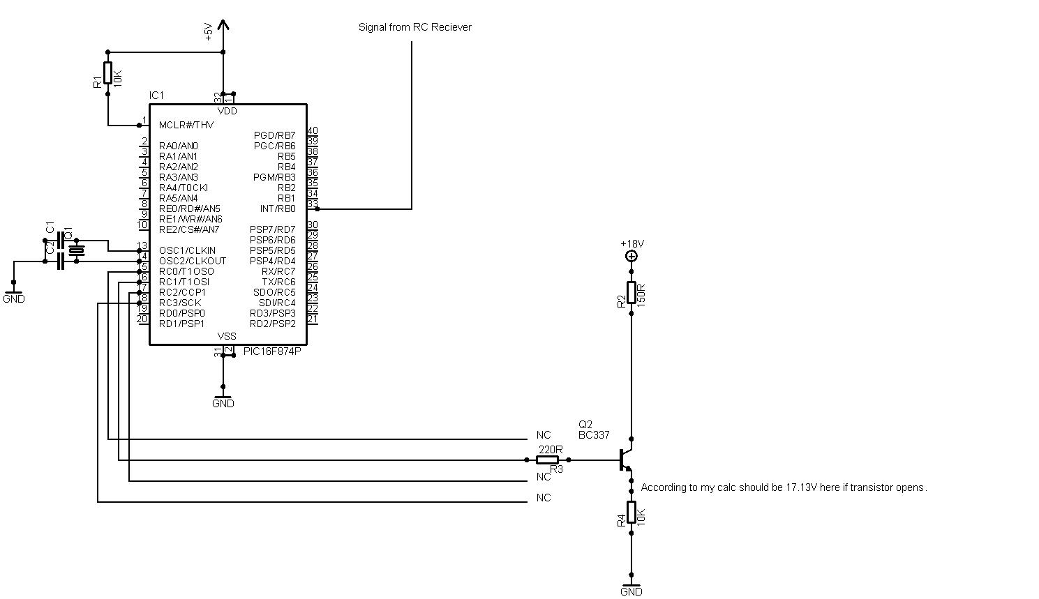
I have written some code on a 16f877 that reads a servo signal and accordingly changes the PWM duty cycle. I do not have a problem with the PWM signal coming out from the PIC. I have checked it on my scope and it is near perfect square and works OK.

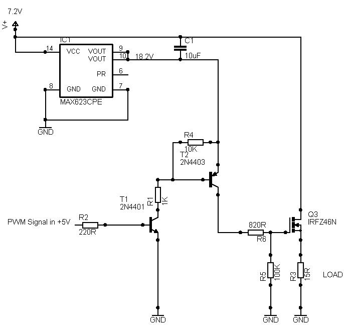
I now feed this signal into a KB817 optocoupler and the strange thing is it then just jumps from 0 to full volts. I cannot detect my pwm signal on the other side (transistor). I first had it on 19.53 KHz and thought the frequency maybe too high for the optocoupler and lowered it to 4.3KHz. But still the same problem. Can anyone please give me some explanation and maybe which optocoupler I should use then.


Regards

Nic
 

6n136 problem

Hi Friend,
First KB817 is not a good optocoupler for this application, it is for general purpose.
You better use a 6N137, it is a faster than KB817. You can use a
optodrivers like TLP250 (Toshiba) too.
Second you must put a some driver between PWM outputs
and optocoupler inputs.
Best regards: Taner

:D
 
irfz44n+pic+pwm

Taner said:
Hi Friend,
First KB817 is not a good optocoupler for this application, it is for general purpose.
You better use a 6N137, it is a faster than KB817. You can use a
optodrivers like TLP250 (Toshiba) too.
Second you must put a some driver between PWM outputs
and optocoupler inputs.
Best regards: Taner

:D

Hi there,

OK, I thought the KB817 is not right for the application. What do you mean that I have to put a driver between PWM outputs. The PIC PWM output should be enough for the leds in the opto coupler should it not? On the other side I do have a MAX622 driving the MOSFETS I have. But I did not even couple the mosfets yet, I just connected my scope directly on the other side of the opto coupler to see if my PWM output gets through, and as I said nothing comes through, not even a warped signal, it just goes straight to maximum.

Regards

Nic

Added after 12 minutes:

Hi guys,

The problem above is for a speed controller I want to design for my sons RC car. I am doing it to learn C on the microcontroller and to learn more about electronic design.

So I have another question if I may: I have the opto-couplers in there so that I can seperate the motor noise from the microcontroller. My problem is that I only have one battery to do this from, so at the moment my ground plane is the same for the microcontroller and for the Mosfet bridge. How is this done, if you do not have two sources of power to seperate the two parts of the design totally.

Do I need the opto couplers? Or would transistors do the trick?

Regards

Nic
 

+tlp250+calculation

Hi ScratchBuild,

Your first problem is solved by using a correct optocoupler you can use 4N25 or CY17 for this operation i have also used it you should add a 220Ω Resistance in your path

and for the second problem just add a diode in prallel in reverse biased position accross you MOSFET all noise will chose the path of diode so your system will work fine with the single battery please tell voltage of your motor; you may not need the optocoupler
Thanks
 

pwm irfz44n

Hi there,

My battery is a 7.2V and I suppose the motor is 12V. I do not have specs on it. But if I can do without the optocoupler it would be great. Is the 220R resistor to limit the current in the opto transistor?

I am using IRFZ44N FETS for this design, which already have the bypass diodes incorporated in it.

Regards

Nic
 

4n22 optocoupler application

Hi,
You need to limit the current with a series resistance and on the output side, the collector should be pulled through a resistor to supply and the emitter to ground, to observe the wave form. To reduce further the current through PIC, you can use a more sensitive opto like 4N22 or 6N136 (very fast compared to 4N22).
Regards,
Laktronics
 

pwm 7.2v motor

Hi there,

As I said at the top, I am still learning so please bear with me.

I have taken out the opto coupler for now and are testing just with a BC337 transistor but it does not work as I think it should. The 18.1 V gets generated from a max622 voltage pump from 7.1 V which generates VCC + 11V.

The BC337 I have has a Hef of 338. So the maximum allowed current through the transistor would be
I = V/R * Hfe = ((5-0.7)V/0.019A) * 338 = 6.6A
This is way above what the 150R resistor would allow.

I = V/R = (18.1 - .7)/(10K + 150R) = 120mA

According to my calculation now the current through the transistor would be

I= V/R = (18.1-.7)/(10K + 150R) = 1.7mA

But if I measure at the emitter of the transistor I should get

V=17.3 * (10k/(10k + 150r) = 17.044V

if the transistor is driven to saturation.

Well, My PWM signal is perfect just after the 220R resistor and measures about 4.2V at the base of the transistor.

But when I measure at the transistor's emitter I find that I get more or less the same voltage as at the base of the transistor. I still see the PWM signal but it levels out at about 4.2 - 4.4 Volt. Why do I not get an 17V PWM signal?

I am a self taught person so if I am not doing things right please let me know. What must I do to drive a MOSFET in this configuration?


Regards

Nic
 

6n136 6n137 better

Hi
As I undestood from your circuit you will never get 17v on your emitter cos the maximum voltage on your base if transistor is on (saturate) will be 4.3 and the voltage on your emmiter when transistor is off will be ground. connect emiter to groung without resistor and connect a resistor to base with considering the output current of micro and then calculate the collector resistor according the transistor beta. consider collector current and power dissipation in its resistor. as y do this your pwm will be reverse so you can put another transistor to make it correct.
 
6n136 microcontroller

Hi there,

So if I understand this correctly you have to pull the voltage up through a pull-up resistor. If your voltage on the base is 5V you are going to get maximum 5V through the transistor if you do not have a pull-up resistor?

Thank you

Nic
 

bc337 pwm current

no. when your transistor is on (saturate) transistor base will be 0.7v (or may be alittle more than or alittle less than this depende on transistor that u choose) more than emitter voltage and collector voltage will be 0.2v greater tham emitter but when transistor is of base will be zero and collector woltage will be equal to vcc that in your circuit is 18v. if you have any problem tell me to send u a circuit schematic and explain whole in that.

good luck
 

Re: PWM problem

Hi there,

I am now at least getting a square PWM signal if I hookup my oscilloscope accross the 15Ω Load (Wirewound Resistor). My biggest problem is that my frequency for the PWM was too high. I worked at 4.88Khz and now brought it down to 1.22Khz. It looks much better now. Here is my schematic as I use it now.


I hope I have covered all the current limits.

I now have a new problem. As soon as I start increasing the duty cycle the voltage starts dropping from 7.2V down to 2.5V. Why is this. I am measuring occross the 15Ω load. I cannot find the reason for this. I know it is easy for a seasoned electronics guy but I am obviosly missing something somewhere.

Regards

Nic
 

Re: PWM problem

My friend how you measure the voltage on resistor? and can u say me what do you want to do? why you have used so much components?
 
Re: PWM problem

Hi there,

The 15Ω resistor I just use as a dummy load to see if I get the right PWM signal over my load.

This is the high side of a H-bridge I want to build, so the 15Ω resistor would be a motor in the end.

The reason I use two transistors to drive the mosfet is to protect the µC pin from the high voltages I need to drive the Mosfet. And if you have only one transistor the signal would in any case be inversed.

I know I can rather just use a opto-coupler in place of the two transistors but I do not have such a fast Opto-Coupler available. I am intending to use something like a 6N136.

Regards
Nic
 

Status
Not open for further replies.

Similar threads

Part and Inventory Search

Welcome to EDABoard.com

Sponsor

Back
Top