Continue to Site

Welcome to EDAboard.com

Welcome to our site! EDAboard.com is an international Electronics Discussion Forum focused on EDA software, circuits, schematics, books, theory, papers, asic, pld, 8051, DSP, Network, RF, Analog Design, PCB, Service Manuals... and a whole lot more! To participate you need to register. Registration is free. Click here to register now.

ad594 with j thermocouple

Status
Not open for further replies.

tictac

Full Member level 5
Joined
Oct 22, 2006
Messages
297
Helped
3
Reputation
6
Reaction score
3
Trophy points
1,298
Location
Polland
Activity points
3,572
ad594 application

hi

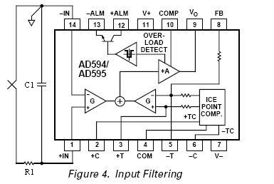
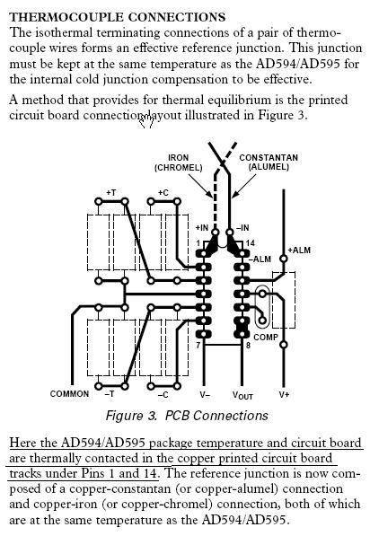
I use AD594 to amplify one J thermocouple .I study ad594 datasheet.but I didnt realize about one part of this datasheet.I send the picture of that part.in this picture two tracks come to pin 1,14 from thermocouple's pin. why does tracks connect together ? and also I didnt realize this paragraph that relate to the picture.

"Here the AD594/AD595 package temperature and circuit board are thermally contacted in the copper printed circuit board tracks under Pins 1 and 14."

what can I do to decreae noise for this circuit.I use one 100k resistor from positive lead of thermocouple to pin 1 and one 100nf cap from pin 1 to ground.does the value of them is correct??
can any one send me schematic and pcb for ad594 with Noise Suppression please.


42_1197500658.jpg


by regards
 

ad594 circuit interference

pleae help me
 

First of all, tracks are not connected together, this picture just shows the thermocouple wires and the thermocouple itself ..

Under no circumstances should you connect anything between the thermocouple leads and the input pins (1 and 14) .. no resistors, no capacitors, nothing ..
If you do, you will create another junction and this will affect the output voltage ..
If you need to decrease noises, try to shield the thermocouple wires (they shouldn't be longer than 500mm) or "play" with compensation capacitor connected between pins 10 and 9, 11 .. see figure.5 .. or add another LPF stage after the AD594 ..

Regards,
IanP
 

    tictac

    Points: 2
    Helpful Answer Positive Rating
Hi IanP and thank you so much

"add another LPF stage after the AD594 "

can you describe it a little?

Regards,

Added after 40 minutes:

hi
I use R1=1k C1=100nf
are this value correct ,I think resistor with this value increase offset voltage.
please give value for them that proper for filtering

regards

Added after 2 minutes:

sorry
I forget to send its picture
74_1197632331.jpg
 

Connecting R-C network between a thermocouple and the AD594 input pin is incorrect ..
Thermocouples have to be wired directly to the AD594 - nothing in between ..

Maybe you should consider a simple double-pole low-pass active filter, as described here:
**broken link removed**
with ≤10Hz cut-off frequency ..

Regards,
IanP
 
  • Like
Reactions: vijjy471

    tictac

    Points: 2
    Helpful Answer Positive Rating

    vijjy471

    Points: 2
    Helpful Answer Positive Rating
I do proper application note for ad594 and in this app note say that filter betwean ad594 and thermocouple

Added after 2 minutes:

I cut off above picture from app note

Added after 53 seconds:

and thank you for link
its very usefull
Regards
 

It probably is possible to put a filter between the AD594 and the thermocouple, but as IanP states -- you're much better off just connecting the thermocouple to the AD594. You will most likely introduce additional problems unless you are very careful (you are introducing additional junctions, leakage, series resistance, etc...)
 

    tictac

    Points: 2
    Helpful Answer Positive Rating
I test this circuit with R=100k C=100nf and OP07.but the output of ad594 goes very high and show abnormal temp

Added after 3 minutes:

when I connect the thermpcouple to the ad594 without any RC filter the output goes very low and have a unstable output.in this situatuin I connect the pin 14 of ad594 to ground and it was correct

Added after 1 minutes:

I test this circuit on the bread board

Added after 17 minutes:

the output of thermocouple is about uV but when I use above circuit the output of opamp is about 1.2v and this voltage make an error for ad594
 

Where are you measuring 1.2V -- at pin 9?

Also, what do you have connected to pins 6 and 7? You need to have another thermocouple there that is held at a temperature equal to the freezing point of water.
 

    tictac

    Points: 2
    Helpful Answer Positive Rating
output of the opamp that connect to input pin of ad594 is 1.2v .and I didnt connect anything to pin 6 and 7 of ad594
 

I've you've got a separate opamp connected between the thermocouple and the AD594, you need to be careful of anything that is going to produce a voltage offset. Since the thermocouple voltage signal is on the order of 10's of uV, you must be very careful to limit things like voltage offset, etc..
My advice would be to connect the thermocouple directly to pins 1 and 14 of the AD594. If you are experiencing interference, you can shield the thermocouple wires.
 

    tictac

    Points: 2
    Helpful Answer Positive Rating
thank you,finally I directly connect pin 1,14 to thermocouple.it works.

Added after 4 minutes:

I connect pin 14 to ground,is it correct?
 

Yea - you should be able to connect 14 to ground, provided you have powered the part from plus/minus voltage rails.
 

    tictac

    Points: 2
    Helpful Answer Positive Rating
i m having a problem connecting ad595 with 80mega16 microcontroller.please help me in understandng what pin to connect with what.a pin connection diagram would help..having a tough time deciphering the data sheet.studnt of mechanical engineering..assigned a DAQ minproject.

thank
 

AD594 with j thermocoupler

Connecting R-C network between a thermocouple and the AD594 input pin is incorrect ..
Thermocouples have to be wired directly to the AD594 - nothing in between ..

Maybe you should consider a simple double-pole low-pass active filter, as described here:
**broken link removed**
with ≤10Hz cut-off frequency ..

Regards,
IanP

am connecting j type thermo coupler to the pin 1 and 14 i get lot of variations in temprature(5 to 30 deg at 32 deg) but when am using R-C filter(R=10K,C=100nf) i'll get(34 to 36 deg) variatoins for same 32 deg temperature tell me any solution to get constant temprature...............
Regards,
Laxmikanth
 

Status
Not open for further replies.

Similar threads

Part and Inventory Search

Welcome to EDABoard.com

Sponsor

Back
Top