Continue to Site

Welcome to EDAboard.com

Welcome to our site! EDAboard.com is an international Electronics Discussion Forum focused on EDA software, circuits, schematics, books, theory, papers, asic, pld, 8051, DSP, Network, RF, Analog Design, PCB, Service Manuals... and a whole lot more! To participate you need to register. Registration is free. Click here to register now.

What is the maximum frequency that 741 Op-Amp can deal without problems?

Status
Not open for further replies.

gameelgamal

Member level 5
Joined
Dec 14, 2006
Messages
85
Helped
0
Reputation
0
Reaction score
0
Trophy points
1,286
Location
Egypt
Activity points
1,888
Hi....
I want to apply a signal with a frequency of 40 kHz to 741 op-amp for amplifying it with a gain of 100.
My question is: Can 741 Op-Amp do that??
In other words, What is the Max frequency that 741 Op-Amp can deal with without problem???


Another question, Can I connect the negative supply pin of the OP-Amp to GND???
 

741 frequency response

No you cannot connect the negative pin to ground as the 741 stops short about 1.5 volts between +rail and ground.
The 741 will happily amplify 40 khz providing your coupling is correct .
 
what are the specifications of 741 op-amp

For future reference, if you look at the 'GainBandwidthProduct' specification in the data sheet and divide this parameter by the gain you need, this will be the -3dB point frequency rolloff.
For example:
GainBandwidthProduct = 100MHz.
Gain = 100.
Frequency response of op-amp,
100MHz/100 = 1MHz.
Response will be -3dB at 1MHz.

The 741 was one of the first general purpose op-amps. A bit long in the tooth now.
There are a lot of single supply rail to rail op-amps you can choose from these days.
 
minimum single supply 741

f you look at the 'GainBandwidthProduct' specification in the data sheet and divide this parameter by the gain you need, this will be the -3dB point frequency rolloff

First, I have red the data sheet ,but I didnt find the 'GainBandwidthProduct' value,So could you tell the 'GainBandwidthProduct' for the 741
Second, could you explain what do you mean by the -3dB point frequency rolloff
 

how to connect a 741 op amp

Modern data sheets call it GainBandwidthProduct, older data sheets may just call it Bandwidth.
For a 741 its 1.5MHz. The Bandwidh is related to the Rise Time, or how fast the op-amp can swing its output.
If you measure the frequency response of your amplifier circuit, it will start to roll off at higher frequencies, when the gain has fallen by -3dB, then that point is the Frequency Bandwidth of your amplifier circuit.
For a 741 it will be:
1.5MHz/100 = 15KHz.
So the frequency response of your circit using a 741 with a gain of 100 will be flat up to 15KHz and then start to roll off. The 741 is not a good choice for a circuit with a gain of 100 at 40KHz!
 
connectiong an 741 opamp

Modern data sheets call it GainBandwidthProduct, older data sheets may just call it Bandwidth.
Tgats right, my datasheet belongs to the older ones :D


Just one more question, what do you mean by
it will start to roll off at higher frequencies
In other words , What will happen if I connect 40 KHz signal to 741 chip,????
 

ac coupled opamp

If you have a 741 circuit with a nominal gain of 100 at midband and no other reactive components that affect the frequency response, (like capacitors in the feedback loop) you can expect the gain to start to fall with rising frequency and be 3dB down at 15KHz, it will continue to fall with rising frequency at about 6dB per octave, so it will be 9dB down at 30KHz, which has reduced your gain to about 35, at 40KHz the gain would have fallen to about 25.
I suggest a better choice of op-amp would be a TS922 type. This has a GainBandwidthProduct of 4MHz and is a single supply rail to rail in/out op-amp.
 
741 one rail and ground

If you don’t mind, Could you look at the circuit below, which what I'm trying to do,
The UltraSonic transducer generate a small signal with afrequency of 40 KHz , This signal will be applied to a single supply Op-Amp (Lm6172) which will amplify the signal with a gain of 100 (100 kΩ/1 kΩ )
The signal is applied to the Op-Amp through a high pass filter (0.02 uf & 3 kΩ)
My question is : What is the needing of the voltage divider, I mean why we don’t connect the 1 kΩ to Gnd , as any conventional non inverting amplifier???
 

741 op amp specs

gameelgamal said:
My question is : What is the needing of the voltage divider, I mean why we don’t connect the 1 kΩ to Gnd , as any conventional non inverting amplifier???

This amp is not rail to rail, meaning it has some minimum voltage between power supply and input to operate. In this case 300mV. Refer to common mode input voltage range at the begining of data sheet.
Voltage divider places both inputs at 2.5V so it has enough room to operate. I would add some capacitor to ground from that point just to make sure.
 
741 op amp single supply

You bias the input to half the rail voltage because it is an AC coupled amplifier and the output needs to swing about the midpoint. Be aware that the output will also be biased to half the rail, 2V5.
The transducer signal is referenced to ground so you need to bypass the lower 10K with a capacitor to couple your 1K feedback resistor to ground, otherwise the 10K will reduce the gain to ~10. If you put a 1uF capacitor across the lower 10K resistor, this will AC couple the 1K to ground and then it should work ok.

Also put a 100nF cap close to the power supply pin of the op-amp to decouple the op-amp power supply.
 
741 amplifier

ok, I will use CA3140 OpAmp instead of LM6172 OpAmp (because I didnt find the last one)
It is also a single supply OpAmp

**broken link removed**

Am I still needing the voltage divider or not???
 

741 frequency response circuit

Yes, you still need the voltage divider for an AC amplifier.
You also need a capacitor on the output to block the 2v5 DC bias and pass the AC signal. It's value will depend on what this stage is driving.
 
741 op amp frequency

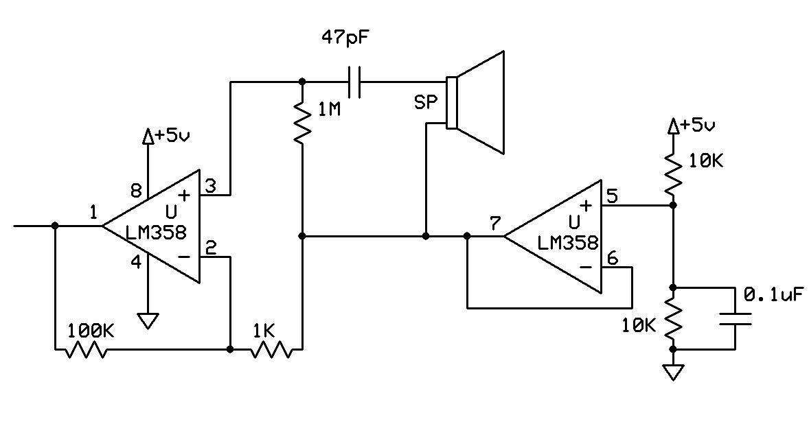
Sure you do. You are forgeting that signal can be negative in respect to your 0V. To follow that output would have to swing to negative value, but it can't go beyond rail voltage. Divider places both your inputs and output to midle point between rails and allows your opamp to work for both positive and negative value of your signal. In your place I would use some opamp that has dual amp in 8 pin case and use second amp to create "virtual ground" at 2.5V as shown on schematics bellow.

71_1196112972.jpg


Also, note much higher value of resistor loading your piezo transducer. Piezo will typically have very high impedance and in order to get 40kHz signal separated without too much loading you need to increase value of resistance. Capacitor is changed to match corner frequency of 4kHz. If you don't care if lower frequencies are going through, just ommit capacitor and increase resistor loading your transducer.

These are very basic circuits, I would recomment you searching EDAboard for links on opamps readings for beginners.
 
741 single power supply

check:

**broken link removed**

Cheers
 
Status
Not open for further replies.

Similar threads

Part and Inventory Search

Welcome to EDABoard.com

Sponsor

Back
Top