Continue to Site

Welcome to EDAboard.com

Welcome to our site! EDAboard.com is an international Electronics Discussion Forum focused on EDA software, circuits, schematics, books, theory, papers, asic, pld, 8051, DSP, Network, RF, Analog Design, PCB, Service Manuals... and a whole lot more! To participate you need to register. Registration is free. Click here to register now.

lpt pin motor control

Status
Not open for further replies.

renegat

Newbie level 3
Joined
Nov 3, 2007
Messages
4
Helped
0
Reputation
0
Reaction score
0
Trophy points
1,281
Activity points
1,310
lpt motor control

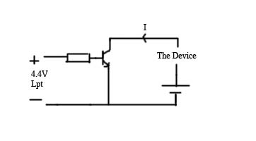
LPT pin produces 4,4V. I don't know how many mili-ampers it will give me with 1kohm resistor... but i know that not much.
I want to control by lpt pin motor of a toy. To do so i must use external power source. I want use 3 batteries that will produce 4,5V.

Lpt pin number 2 will control transistor. The pin will be attached to the base of npn transistor bc237.
Lpt pin gives 4,4V at '1' logic, and 0,9V at '0'. Now there's a problem, because as much as i know transistor doesn't work only below 0,7V. I don't know which resistor i should connect to the base, so the valtage would drop to the (i don't know 0.5V?).
 

lpt pin number

Dear Renegat, you may use any resistor available as you just have to provide a current path to the base, so use what ever you have...preferably use between 300Ohms and 5KOhms...1KOhm is quite common so you may use that ... the reason for mentioning you a maximum limit is that above this the current will decrease too much and it would be quite difficult for the transistor to operate ...
so 1KOhom Recommended...

Best Regards
 

Thank you very much. Now I think i know everything. I hope the scheme will work. The device means motor. I thought that using transistors would be a mess, but i think in that case it is very easy.

hope it will work (with 1kohm resistor).
55_1194128281.jpg
 

yup it will work...just one thing...in the image you didn't mention the place of motor...you motor should be located between the Emitter and the Ground...

Do Click Helped Button if you feel like i helped...thanks...


Best Regards
 

    renegat

    Points: 2
    Helpful Answer Positive Rating
Well i thought that the motor could be placed anywhere in the circuit to the right of transistor. By 'the device' i meant the motor. What if i would leve it between plus side of battery, and collector. It will not work?
 

Well connecting one terminal of the motor to the positive terminal of the battery and the second terminal to the collector will turn the motor on constantly...as when there's a logic 0 or low potential on the base this means that the base is grounded, emitter is grounded and as theres no high potential on the collector so the collector will be at a lower potential providing a path for the battery to conduct thus the motor will be operating and you won't be able to stop it...

Best Regards
 

Thanks. It really helped me a lot. Now I think i understand how the bipolar transistor works. I just didn't know that collector must've the higher potential than emiter.

Once again, thank you very much!

PS. Just out of curiosity. The scheme (without any changes - from image) will work on nmos transisotr? Or there should be also done changes as with bipolar transistors.
 

Status
Not open for further replies.

Part and Inventory Search

Welcome to EDABoard.com

Sponsor

Back
Top