Continue to Site
Follow along with the video below to see how to install our site as a web app on your home screen.
Note: This feature may not be available in some browsers.
diegor747 said:Hi all users
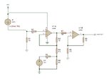
i neet to convert a 4/20mA Sensorsignal
to a 0-10V Signal
is there a simple schematics for this.
thanks
diegor747
james said:diegor747,
You may have to replace the generator V1 with a band-gap 2.5 diode for better circuit stability.
Hope this help
artem said:P.S. I assume Opamp are supplied with negative and positive voltage relative to ground (+ 15 V and -15 V)