Continue to Site

Welcome to EDAboard.com

Welcome to our site! EDAboard.com is an international Electronics Discussion Forum focused on EDA software, circuits, schematics, books, theory, papers, asic, pld, 8051, DSP, Network, RF, Analog Design, PCB, Service Manuals... and a whole lot more! To participate you need to register. Registration is free. Click here to register now.

Help me solve a problem about simulating 2x16 LCD drive in Proteus

Status
Not open for further replies.

mtkee2003

Full Member level 2
Joined
Sep 24, 2005
Messages
132
Helped
4
Reputation
10
Reaction score
1
Trophy points
1,298
Activity points
2,356
hi

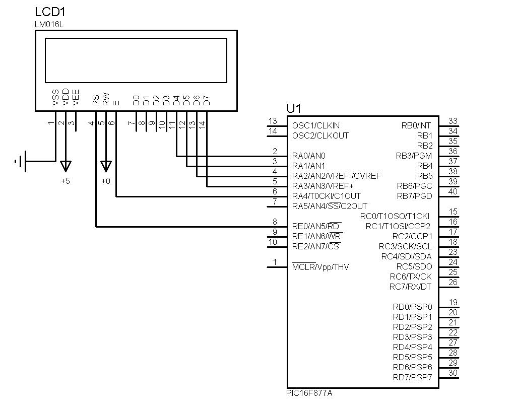
recently i drove a 2x16 LCD. it works in real world but proteus can't simulate this program. i attach its simulation files + section file + hex file + its source file that i wrote with PICBASIC PRO Compiler.

53_1178176939_thumb.jpg


can anyone help me?

with best regards.
 

Re: proteus bug report

Maybe the bug is in your project :wink:

Schematic:
Connect RS to RA4 (not RE0).
Connect E to RB0 (not RA4).
Connect a 4.7k pull-up resistor between RS and +5V.

Program:
Uncomment DEFINE LCD_COMMANDUS 2000
Uncomment DEFINE LCD_DATAUS 50
Change DELAY to 500

Run your simulation again, should be working now!
 

Re: proteus bug report

I think, your RS pin from LCD1 is connected to a floating pin on pic (RE0) and your code is putting RB0 to ground.

are you supposed to connect RS to RB0 ?

I don't know basic pro, I use C. Make sure you're initialising LCD properly in your code (with specified minimum delays).

I've simulated same lcd with 8051 and I'm sure, there is no bug in Proteus.
 

Re: proteus bug report

The problem my friend is your schematic.

Here is the original diagram:

41_1178160055.jpg


Here is the modified diagram:

31_1178160148.jpg


You can see that i added a resistor at pin RA4, the reason for this is that RA4 is an open drain pin so you need a pullup resistor.

I've also observed that your program dictates that the RS pin of the LCD is connected to RA4 not RE0. The E pin of the LCD is connected to RB0 not RA4.

Code:
'****************************************************************
'*  Name    : UNTITLED.BAS                                      *
'*  Author  : [select VIEW...EDITOR OPTIONS]                    *
'*  Notice  : Copyright (c) 2007 [select VIEW...EDITOR OPTIONS] *
'*          : All Rights Reserved                               *
'*  Date    : 2007/05/02                                        *
'*  Version : 1.0                                               *
'*  Notes   :                                                   *
'*          :                                                   *
'****************************************************************
DEFINE OSC 16

DEFINE LCD_DREG PORTA
DEFINE LCD_DBIT 0

DEFINE LCD_RSREG PORTA
DEFINE LCD_RSBIT 4

DEFINE LCD_EREG PORTB
DEFINE LCD_EBIT 0

DEFINE LCD_BITS 4
DEFINE LCD_LINES 2
'DEFINE LCD_COMMANDUS 2000
'DEFINE LCD_DATAUS 50

'OPTION_REG.7=0

'C VAR BYTE

'TRISD=%01010101
'PORTD=%11111111

'C=PORTD

'TRISC=%00000000
'PORTC=PORTD

PAUSE 1
lcdout $FE,1,"HELLO"

:D
 

    mtkee2003

    Points: 2
    Helpful Answer Positive Rating
proteus bug report

hi all

i'm sorry, but i have a mistake in uploading some files. now its corrected.

but i want to use only PORTE and PORTA. (not PORTB).

with best regards.
 

Re: proteus bug report

Then use the code below:

Code:
'**************************************************************** 
'*  Name    : UNTITLED.BAS                                      * 
'*  Author  : [select VIEW...EDITOR OPTIONS]                    * 
'*  Notice  : Copyright (c) 2007 [select VIEW...EDITOR OPTIONS] * 
'*          : All Rights Reserved                               * 
'*  Date    : 2007/05/02                                        * 
'*  Version : 1.0                                               * 
'*  Notes   :                                                   * 
'*          :                                                   * 
'**************************************************************** 
DEFINE OSC 16 

DEFINE LCD_DREG PORTA 
DEFINE LCD_DBIT 0 

DEFINE LCD_RSREG PORTA 
DEFINE LCD_RSBIT 4 

DEFINE LCD_EREG PORTE
DEFINE LCD_EBIT 0 

DEFINE LCD_BITS 4 
DEFINE LCD_LINES 2 
'DEFINE LCD_COMMANDUS 2000 
'DEFINE LCD_DATAUS 50 

'OPTION_REG.7=0 

'C VAR BYTE 

'TRISD=%01010101 
'PORTD=%11111111 

'C=PORTD 

'TRISC=%00000000 
'PORTC=PORTD 

PAUSE 1 
lcdout $FE,1,"HELLO"

Replace lcd E pin to PortE.
 

    mtkee2003

    Points: 2
    Helpful Answer Positive Rating
proteus bug report

hi

thank you for your help.

but now i have new amazing problem!
i want to connet RS to RA4 and E to RA5 and data bus to RA3:RA0, but it doesn't work! is it a bug in PICBASICPRO?

with best regards.
 

proteus bug report

HI

i have solve my problem. i should initialize ADCON1.

with best regards.
 

Status
Not open for further replies.

Similar threads

Part and Inventory Search

Welcome to EDABoard.com

Sponsor

Back
Top