Continue to Site

Welcome to EDAboard.com

Welcome to our site! EDAboard.com is an international Electronics Discussion Forum focused on EDA software, circuits, schematics, books, theory, papers, asic, pld, 8051, DSP, Network, RF, Analog Design, PCB, Service Manuals... and a whole lot more! To participate you need to register. Registration is free. Click here to register now.

keypad 4x4 &lcd probs!!

Status
Not open for further replies.

nuarizzah

Junior Member level 1
Joined
Mar 29, 2006
Messages
17
Helped
0
Reputation
0
Reaction score
0
Trophy points
1,281
Activity points
1,429
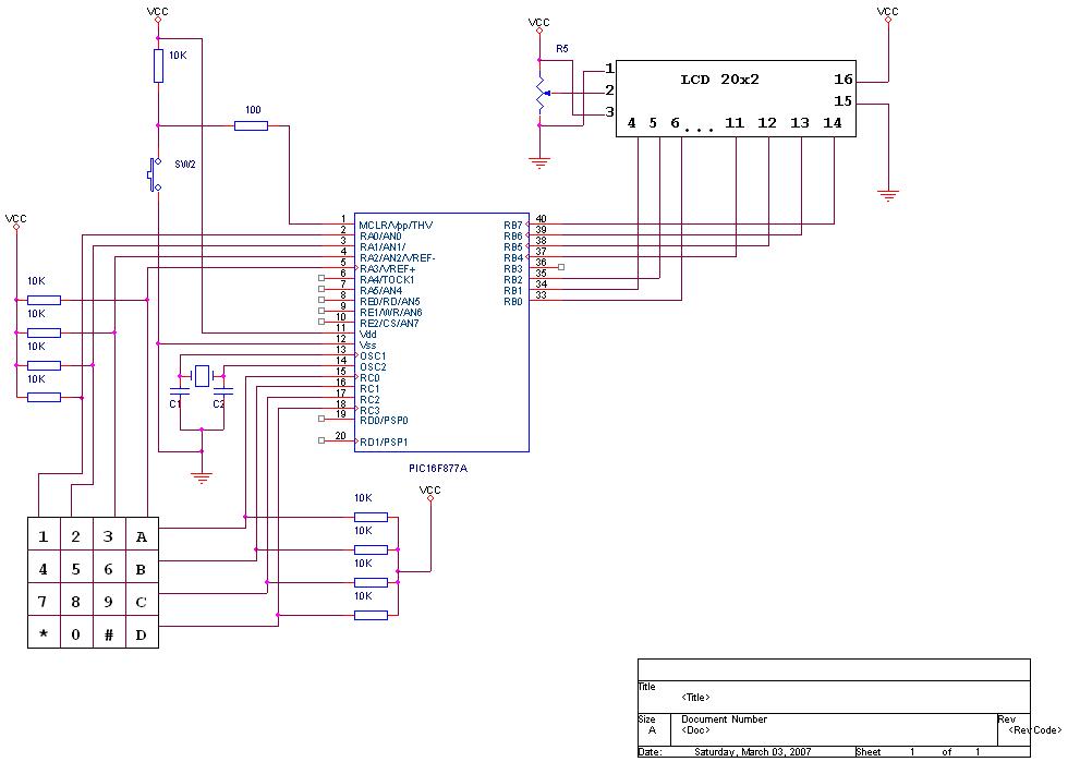
1. i'm doing programming for keypad 4x4 with pic16f877 (PIC C compiler) but the problem is the character that i enter did'nt appear on the lcd. the lcd also got few problems...sometimes it's function well as programmed but few minutes after that strange characters appeared...does anyone know about this??...

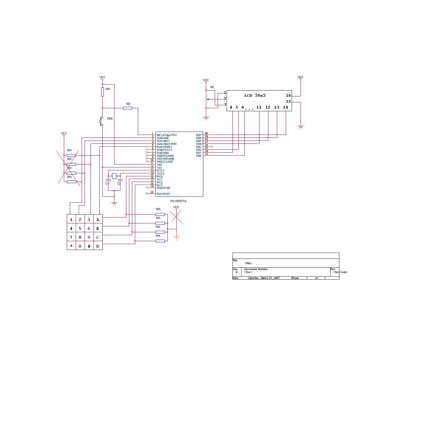
2. then, i've chganged the programmed and used the one with header file for keypad(kbd.h). but i realized that this header file is for 4x3 keypad..but i'm not sure about this??.. does anyone have any idea??but still nothing happpened to the keypad.!!! help please!!!

thankz.....very much...
 

Hi!
If u share ur code then we will be in a better position to help.
By the way which compiler are you using, PICC byCCSC i guess?
Regards.
 

    V

    Points: 2
    Helpful Answer Positive Rating
if you have probs with keypad, use a key encoder with it. See the circuit here, only one 74922 is required
**broken link removed**

If you use key encoder, no probs will occur related to key debouncing

bibin john
ADVERTISING LINK REMOVED
 

LCD is showing garbage value because it has got false data and control signals. It can happen in many ways. Please check the foolowing:

1. Did u check the interface connection to LCD? Sometimes it may be due to loose solder connection or loose contact at data/control pins.

2. Is your circuit doing any other operation?Is the garbage value coming after any particular operation?It can happen that your LCD is triggered by switching of some other circuits in your system. In this case you have to take necessary steps to protect your LCD from external interference.

3.Is your micro-controller getting reset at this point?


4. Are you using the ports where your lcd/keyboard is connected for some other application?

5. Is the ports having internal pull ups? Sometimes Keyboard's require external pull up.
 

I dont think there could be real inputs to your problem unless you share the schematics and code or more details as mentioned by "Prajit"
May be you are not issuing LCD clear command, and other commands
 

here is the code and circuit...sorry for the 'terrible' drawing...
please check for me. tq....!!!

Code:
//USE PORTB FOR LCD,
//USE PORTA (a0,a1,a2,a3) FOR KEYPAD IN
//USE PORTC (c0,c1,c2,c3) FOR KEYPAD OUT

#include<16f877a.h>
#use delay(clock=20000000)
#fuses hs,noprotect,nowdt,nolvp

#byte porta=5
#byte portb=6
#byte portc=7

#define use_portb_lcd TRUE
#include<lcd.c>

int indata;


//row detection module
void getkey()
{
   indata=0;
   if(input(PIN_C0)==0)
   {
      indata=0;
   }
   else if(input(PIN_C1)==0)
   {
      indata=1;
   }
    else if(input(PIN_C2)==0)
   {
      indata=2;
   }

    else if(input(PIN_C3)==0)
   {
      indata=3;
   }
}

void main()

{
   int mysta;
   byte i;
   byte k;

   setup_port_a(NO_ANALOGS);
   set_tris_a(0x00);
   set_tris_c(0x8F);

   lcd_init();

   lcd_putc("\fTRIAL1...!!!\n");
   delay_ms(1000);

   do
   {
      mysta=0;

      //ENABLE 1ST COLUMN
      porta=0xF7; //11110111
      getkey();

      if(indata==0)
      {
         k=1;
         mysta=1;
      }

       else if(indata==1)
      {
         k=4;
         mysta=1;
      }

        else if(indata==2)
      {
         k=7;
         mysta=1;
      }

       else if(indata==3)
      {
         k='*';
         mysta=1;
      }

      if(mysta==1)
      {
         lcd_putc(k+'0');
         delay_ms(500);
         mysta=0;
      }

     //ENABLE 2nd COLUMN
      porta=0xFB;//11111011
      getkey();

      if(indata==0)
      {
         k=2;
         mysta=1;
      }

       else if(indata==1)
      {
         k=5;
         mysta=1;
      }

        else if(indata==2)
      {
         k=8;
         mysta=1;
      }

       else if(indata==3)
      {
         k=0;
         mysta=1;
      }

      if(mysta==1)
      {
         lcd_putc(k+'0');
         delay_ms(500);
         mysta=0;
      }

     //ENABLE 3rd COLUMN
      porta=0xFD;//11111101
      getkey();

      if(indata==0)
      {
         k=3;
         mysta=1;
      }

       else if(indata==1)
      {
         k=6;
         mysta=1;
      }

        else if(indata==2)
      {
         k=9;
         mysta=1;
      }

       else if(indata==3)
      {
         k='#';
         mysta=1;
      }

      if(mysta==1)
      {
         lcd_putc(k+'0');
         delay_ms(500);
         mysta=0;
      }

     //ENABLE 4th COLUMN
      porta=0xFE;//11111110
      getkey();

      if(indata==0)
      {
         k='A';
         mysta=1;
      }

       else if(indata==1)
      {
         k='B';
         mysta=1;
      }

        else if(indata==2)
      {
         k='C';
         mysta=1;
      }

       else if(indata==3)
      {
         k='D';
         mysta=1;
      }

      if(mysta==1)
      {
         lcd_putc(k+'0');
         delay_ms(500);
         mysta=0;
      }


 }while(1);
}

 
Last edited by a moderator:

good day sir,.
can you give me a source code for 4x4 keypad, so that my PIC UPRC from e-gizmo will acknowledge my 4x4 keypad and its functions,.

Thank you verry much,. :grin:
 

here is the code and circuit...sorry for the 'terrible' drawing...
please check for me. tq....!!!


I think your problem is circuit diagram
You are connect to key s both sides to +vcc. (When you press keys, outputs not change.)

 
  • Like
Reactions: Daham

    Daham

    Points: 2
    Helpful Answer Positive Rating
thanks a lot,. but where is the code i needed to recognize the inputs from the keyboard to the MCU'? that when i press 1 on the keypad it will give the specific value of the 1 to the MCU,.
 

You have rows and columns, either row or column will be outputs. Since all your outputs can go high on its own (No Open drain) you do not need a pull up there. But I don't think it will create any harm provided reasonably high value.
But the inputs need pull downs to be safe from floating. So change the resistors in the input set to pull down.
I feel the pull down can be 47k and pull up if needed can be 4k7.
Contrast pin should be 3 not 2. Also please check the back light pin polarity 15 and 16. In my case normally 16 is GND.
And I think datelines being connected in the lower nibble will be convenient for data transfer. But that may be manageable in the code.
Better to connect a 1uF cap in MCLR pin To GND.

Regards
Roy Thomas


O' This has been mentioned on the above post.
 
Last edited by a moderator:

Status
Not open for further replies.

Similar threads

Part and Inventory Search

Welcome to EDABoard.com

Sponsor

Back
Top