Continue to Site

Welcome to EDAboard.com

Welcome to our site! EDAboard.com is an international Electronics Discussion Forum focused on EDA software, circuits, schematics, books, theory, papers, asic, pld, 8051, DSP, Network, RF, Analog Design, PCB, Service Manuals... and a whole lot more! To participate you need to register. Registration is free. Click here to register now.

circuit simulation software

Status
Not open for further replies.

jsps

Member level 3
Joined
Apr 20, 2006
Messages
61
Helped
1
Reputation
2
Reaction score
1
Trophy points
1,288
Activity points
1,659
ir1150 spice

Hi all,
I need the software in which i can draw ckt dia(analog and digital), and by simulatiing it i want to check voltages and waveforms at different nodes.
Please let me know if anyone having the software and can upload it, or e-mail me at yyuvraj_pune@yahoo.com

regards
JSPS
 

Hi, there are many simulation programms most popular are multisim, orcad and protel
multisim 10 you can download it from the following link **broken link removed**
orcad you can download it from its official page as trial version or recuest cd and last and best(my opinion) protel or altium you can only buy it i think!!! there is no trial version. If you are a beginner i suggest you multisim 10. I hope my suggests helped you.Have a nice day
 

Hey there, PSpice is the software you need....
Download: Student version:

**broken link removed**


need any questions?
 

thanks, if i have any queries i will write to u

Added after 3 hours 55 minutes:

Dear The_edge,
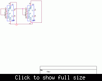
I have downloaded the Pspice Student software with the help of link provided by you.I have drawn one circuit shown below in which I want run each FF with diffenerent clock frequency. and observe the input, outpur waveforms.I am not able to add tools like oscilloscopes and signal generator for clock input.
I am doing this all in OrCad Capture Student (Pspice Student software).
Please advise me how to achieve this?

regards
JSPS


for the digital simulation, i would suggest the "circuit maker " software
too easy to use
 

dear the _edge,
i m waiting for your reply.

regards
JSPS
 

i'm using simplorer it's v very good simulation program you can download it from the site of ansoft
 

JSPS:
download Multisim student version from www.multisim.com. Years ago it was called Workbench. It allows you to drag real instruments to perform your plots (for instance Agilent oscilloscopes) in a easy way.

Hope helps.
 

    jsps

    Points: 2
    Helpful Answer Positive Rating
thanks STOIKOV,
I have downloaded it and using it, but I want to use ICs such as IR1150 (PFC controller) and other ICs which are not in the componenet list diring the simulation, please advise me how to do this.

regards
JSPS
 

you have to look for a spice model in the home page of the company (for example freescale, texas instrument, maxim...). I don't know this exact simulator, but usually all of the simulators can import the spice models or there is an optin to convert these models.
Another options, may be you can find the libraries on web page of multisim.
 

Sorry...

I dont know if you used capture or shematic...
If capture (I would):

First you need to create new project. Click file->new->project, than name it and click OK. In next window select blank project and click OK.

Then draw your FFs.
Than you need to set your simulation profile. clik in menu PSpice->New Simulation Profile, name it click create.
In Transient analysis you have to set "Run to time". Make it several clocks (if your clock is 10u tupe in 100u, or something like that).
Click on "Options" tab, than select "Gate-level Simulation", "Initialize all FFs to" set 0.

Click OK.

Select Place->Part

Type in DigStim1, click OK.
Connect to your FFs clock pin...
Right click on DigStim1, select "Edit PSpice Stimulus". New window opens, name it (lets say clk1), select "clock", click OK, select parameters. (note: MEGA is writen meg, so if you want 10Mhz you type 10meg). Save it, and it will ask you "Update shematic?", click yes. Close it.

Same is for DigStim2.....

Use DigStim for input signal, just dont set it as clock, but as signal...


To see wave forms on some node, select PSpice->Markers->Voltage Level, and put it where ever you want.

Select PSpice->Run...


Sorry for not replying earlier....
 

Status
Not open for further replies.

Part and Inventory Search

Welcome to EDABoard.com

Sponsor

Back
Top