Continue to Site

Welcome to EDAboard.com

Welcome to our site! EDAboard.com is an international Electronics Discussion Forum focused on EDA software, circuits, schematics, books, theory, papers, asic, pld, 8051, DSP, Network, RF, Analog Design, PCB, Service Manuals... and a whole lot more! To participate you need to register. Registration is free. Click here to register now.

The physical concept of phase lead?

Status
Not open for further replies.

fala

Full Member level 5
Joined
Sep 18, 2005
Messages
249
Helped
19
Reputation
38
Reaction score
4
Trophy points
1,298
Activity points
3,569
Hello, I have a problem with understanding the concept of phase lead. I have read the formulas and I know that a high pass filter can introduce a phase lead. I also have read that a low pass filter can produce a phase lag. I don’t have any problem with phase lag. It is very logical because previous state of a wave can be stored in the cap of a low pass filter and introduces a phase lag depending on the RC constant but what I don’t understand is how a cap can speed up the waveform? How it can send a portion of the wave that it had never been received? As I said I know there are mathematical explanations but I need physical explanation, can someone help me please? Thanks a lot.
 

fala,
Phase lag and lead apply only to sinusoidal signals. If signal "A" leads signal "B" by, say, 30 degrees, it simply means that an event such as the positive-going zero crossing of sinusoidal signal "A" precedes the positive-going zero crossing of sinusoidal signal "B" by 30 degrees. Lag and lead must not be confused with delay and anticipation. This can easily be observed on a 'scope. Pass a signal thru a simple RC network consisting of a series capacitor and a shunt resistor. Make the RC time constant equal to 1/(2*Pi*f). The output voltage of the network will lead the input by 45 degrees.
Regards,
Kral.
 
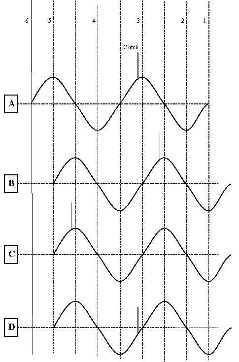
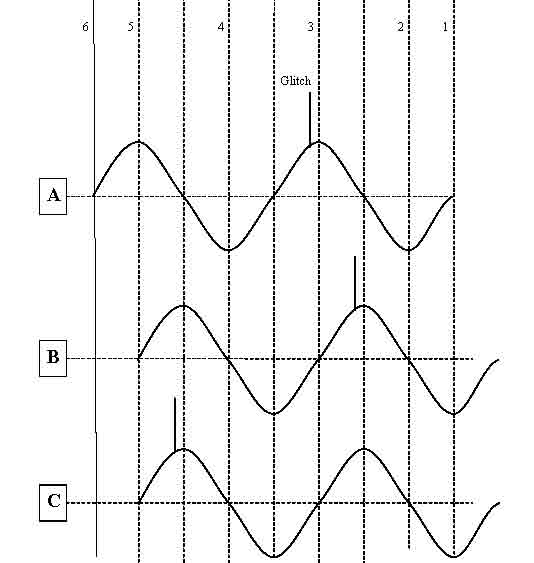
Thank you very much Kral, I’m sorry I still didn’t get it fully. Do you mean that because sinusoidal waves are symmetrical and periodical if a high pass filter causes the output wave to lag input by say 270 degrees it will seem that output leads input by 90 degrees? Let’s assume in the following picture first wave (A) is fed to a high pass filter that introduces 90 degree phase lead. Let’s assume near point 3 of this waveform a glitch occurs. So if I understood you correctly we would have seen the third wave (C) at output of high pass filter rather than second wave (B). In other words the high pass filter actually lags input by 270 degree but because of periodical characteristics of sine wave it seems we have 90 degrees phase lead. Is that right? Something tells me that I did not understand correctly and you will say that No! We see second wave (B) at output of high pass filter. But how? The glitch has not even reached the capacitor of high pass filter, how out put can produce this glitch? Thank you very much for your time.
75_1167753127.jpg
 

fala,
The output of a high pass network can not "anticipate" the input. Remember, the 90 degrees lead applies only to the fundamental frequency, unless the lead network is a pure differentiator. To make the situation easier to visualize, lets assume that the 90 degree lead network is a pure differentiator. At the point in time where the input spike occurs, the output (theoretically) would be another spike starting at the same time the input spike occurs. Remember, the spike consists of an infinite series of high frequency (compared to the fundamental) components. By superposition, the output would be the fundamental (shifted by +90 degrees referenced to the input) plus an infinite number of high frequency sinsusoids, also shifted by +90 degrees referenced to the individual high frequency input sinusoids that comprise the spike.
Regards,
Kral
 
  • Like
Reactions: sharezhao

    fala

    Points: 2
    Helpful Answer Positive Rating

    sharezhao

    Points: 2
    Helpful Answer Positive Rating
Thank you very much indeed Kral. You are helping me to understand something that I could not understand for a long time. If I understood you correctly we should expect a wave like D in output of a differentiator (a single capacitor) and also a high pass filter. We can’t see 90 phase shift of spike immediately but we know it is there. May I ask another question please? For stabilizing Opamps, one way is to put phase lead in feedback loop. Output of Opamp is not necessarily a pure sine wave so how does that work? Thank you very much again.
35_1167761264.jpg
 

fala,
Figure D is correct.
.
Briefly, if an amplifier has a phase lag >= 180 degrees at the frequency where its gain is >= 1, it will oscillate. By putting a phase lead in the feedback loop, you can guarantee that the gain is < 1 at the frequency where the phase shift is >=180. This is done by placing the corner frequency at a low enough point that the phase shift (-90 deg) dominates other phase shifts in the circuit. See section 5 in:
.
https://focus.ti.com/lit/an/sloa020a/sloa020a.pdf
for a clearer and more detailed explanation.
Regards,
Kral
 

    fala

    Points: 2
    Helpful Answer Positive Rating
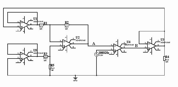
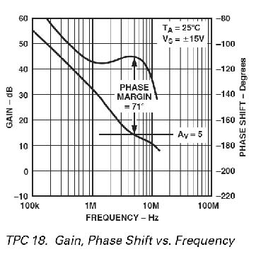
Thank you very much Kral, Thanks for the link. I have a question that had not been addressed at least explicitly in that document. If I have some opamps in feed back loop of another opamp can I place high pass filter(phase lead) to stabilize the opamp. Is my calculation roughly correct? Let’s assume that each opamp(for example OP37) introduces about 80 degree phase shift at 200KHz, so because I have 3 of these opamps in feedback plus the opamp that I want to stabilize itself which makes it four in total , it causes(80 x 4) 320 degrees phase shift which is far beyond stability criteria. So we need at least 185 degrees phase lead to have 45 degrees phase margin. Can we create it by cascading two high pass filters at point A or one at point A and one at point B ?
(In this schematic Op27 has been drawn and frequency has been typed 100K but let's assume opamps are OP37 and frequency is about 200KHz, also another mistake in schematic is that U1(pin3) should be connected to ground and U5(pin3) should be connected to out put of U3(pin6) so voltage of U2 has the same sign as U3 & U4, I apologize for mistakes)
29_1167770294.jpg

OP37 phase shift diagram:
54_1167770972.jpg
 

Hello, Can someone please explain whether the way I used phase lead in above schematic (above post) is right or not? I don’t expect someone to do calculations for me. I just want to know whether I can use high pass filter to stabilize above schematics or not. If errors in schematics are bothering I can post a new error-free schematic. Thanks
 

You know that in feedback configuration amplifier at the output produces signal that controls feedback making controlled signal equal to referent (i.e error tends to be zero)... This Regulating loop works only if until you have negative phase trough loop...
If you have delay trough loop your phase will begin to fall (the effect of low pass filtering). That means that controlled signal will not be same as actual value of referent signal. It will be delayed... If this delay is too big, it can happen that theese two signals are in oposite direction, which makes error too big, making control system unusable because producing oscillations...
Simply loop is not fast enough (phase is dropped too much) to be able to make good control... You then add phase lead(speed up), which readuces this delay and increases stability...
 

    fala

    Points: 2
    Helpful Answer Positive Rating
Thank you very much indeed pixel, All I want to know is: does placing an appropriate high pass filter at point A OR B of the above schematics is a sort of phase lead and indeed improves stability. Of course I understand that the pole frequency introduced by the high pass filter should be calculated by myself to be effective but does generally placing appropriate high pass filter at point A or B improves stability?
Again, Thank you very much for your time.
 

I have lot of things simplified to make clear concept. If you want to make stable loop you have to find loop gain and poles and zeroes...
Loop gain determines the error between controlled an referent signal. Its value should be high, depends on a system (say 80dB)...

Delay (low pass filtering i.e phase lag) is modelled by pole (before pole freq fp, amplitude is not changed, and after it decreases by slope 20dB/dec).
One pole affects the phase in a such way
total phase drop of -90 ( 0 at f<fp/10, -45deg at fp and -90deg at f>10fp)
..

With one pole system you dont have problem closing feedback loop, because your feedback signal will not be in contraphase (-180deg)... Phase can drop -90deg and not more...

Problem becomes when you have two poles...
Then you have design the system in a such way that it acts previous case...
So one pole will be dominant, and other will be put far appart in the area where loop gain is enough attenuated that contraphase effect does not have significtance.
Enough attenuated means not amplifeied... It is the range where loop gain is small (below 1 ie 0dB)...
For stability is important the point where loop gain is exactly 1 and its fc frequancy is called cut-off freq... Phase drop at this point determines how much your system can tollerate additional phase drop until it does not come to contra-phase...
distance from -180deg(contraphase) is called phase margin... It is good to be more than 60 deg, or otherwise in your response you will get peakings...

You can compoensate peakings on many ways, but idea is same:
shape amplitude gain in that non dominant pole stays at the right side of fc
which makes phase margin high enough... >60deg
It can be done if you can:
-shift whole loop gain characteristics to down, by reducing loop gain...
-put far apart poles dominant to left non dominant to the right (pole splitting)

-introduce phase lead at the fc by introducing one negative zero (zero acts like pole but in opposite direction ie increase amplituse and phase characteristics) around fc....

-zero pole cancellation, ie introduce negative zero at the same freq as non dominant pole...
 

    fala

    Points: 2
    Helpful Answer Positive Rating
Thank you very much pixel. As much as I understood by reading your post and also many other application notes, because each opamp is internally compensated to be unity gain stable. Each opamp has two poles(One at lower frequencies which is problematic for stability of the feedback loop and one at higher frequencies for compensation that I guess is not problematic for this particular design). Data for exact position of poles in opamps is not available explicitly in datasheet but rather should be extracted from phase diagrams. From phase diagram of OP37 it is obvious that there are about 80 degrees of phase shift for each opamp, so system is already unstable at working frequency so I can’t add extra poles to reduce gain at higher frequencies. It seems to me that the only way to make this system stable is to introduce phase lead but how? Is it possible to cause as much as I need phase lead using appropriate high pass filters? I mean is the effect of phase lead cumulative so if I put one zero at appropriate frequency using a high pass filter it causes 90 and two causes 180 degree phase lead?
Thanks
 

In every electronic book you have chapter on this topic,
see Razavi's book, Gray-Mayer, Phillp-Allen
Just learn Bode diagrams , and read some examples of componsation...

Also you have theese books..
 

    fala

    Points: 2
    Helpful Answer Positive Rating
Thanks for the link but in all electronic books that I've seen all examples and disscussions are for stability of one opamp which I have no problem with that at all. I never have seen a single book(out of about 5) to discuss about stability of this particular configuration(above schematic). So I have to repeat I have no problem with concept of stability involving one opmp. My problem is to understand how to stablize the above configuration which is completely different because it is already unstable at working frequency(200KHz).
 

It is the same if you know to find loop gain...
How many poles do you have and where are they?

You can see two buffers, that dont affect on dc ,but every of them has one pole...
Also invering amplifier introduces one pole, and also noninverting...
Do you have dominant ?

dc Loop gain=(openlop gain a0)*1*1*1
Amps U1 U2 and U3 have local feedbacks with gain 1: their poles are at amplifiers cutt off freq fc...
So dominant loop pole fd comes from U4 which has open loop gain a0
(it should be given in specifications, and also open loop gain you can find from this eqaution fc=a0*fdom)

For stability is bad if you have tree poles at unity gain freq...
=>
you have to shift cut off freq to the left... (but a0 and fd you can not change supposing that amps are already internally componsated)
you can add capacitance in parallel with resistance (I think R1 )that will make pole after fd and zero before fc, resulting new cut off freq fc1 shifted to the left, and compoensating pole should be eliminated by zero at this freq... and because of that zero has to be before fc1
 

    fala

    Points: 2
    Helpful Answer Positive Rating
A few things,
1- To my understanding I don't have a dominant pole because all opamps are the same OP37 so all poles should be at the same frequency Fc
2-putting a cap in parallel to R1(or R2, R3, R4,R5) will destroy differential amplifier unless you mean that a simillar cap be used in parrallel of resistor corresponding to R1 which is R3
3- Even if I put a capacitor in parrallel to R1 and R3 problem won't go away because phase shift because of U1, U2, U3, U4 are far greater than this. reffering to phase diagram that has been attached it is about 80 degree for each Opamp which makes it (80 x 4) = 320 degree in total. To my knowledge a single capacitor can't lead more than 90 degree so for stability criteria 45 degree phase margin(or as you siad >60 degree phase margin, I need 185-200 degrees phase lead. Thanks
 

fala said:
A few things,
1- To my understanding I don't have a dominant pole because all opamps are the same OP37 so all poles should be at the same frequency Fc
2-putting a cap in parallel to R1(or R2, R3, R4,R5) will destroy differential amplifier unless you mean that a simillar cap be used in parrallel of resistor corresponding to R1 which is R3
3- Even if I put a capacitor in parrallel to R1 and R3 problem won't go away because phase shift because of U1, U2, U3, U4 are far greater than this. reffering to phase diagram that has been attached it is about 80 degree for each Opamp which makes it (80 x 4) = 320 degree in total. To my knowledge a single capacitor can't lead more than 90 degree so for stability criteria 45 degree phase margin(or as you siad >60 degree phase margin, I need 185-200 degrees phase lead. Thanks

1- Like I said U4 does not have local feedback... it works in open loop, and open loop amplifier characeristics have usually dominant pole at really low freq...
say, and high gain. Other works in local feedback with Fc pole...

2-why it would be the problem, you can put additional capacitance, you dont change dc gain
btw do you really need U5?

You can see in this pdf what have I told you...
first comes dominant pole with slope -20dB, than compensatig pole (-40dB)and than zero(-20dB), and than Fc1... see also the phase....
(Fc is located where first -20dB/dec characteristics cut 0dB, and on this diagram sholud be somewhere at 632M)
 

    fala

    Points: 2
    Helpful Answer Positive Rating
pixel said:
fala said:
A few things,
1- To my understanding I don't have a dominant pole because all opamps are the same OP37 so all poles should be at the same frequency Fc
2-putting a cap in parallel to R1(or R2, R3, R4,R5) will destroy differential amplifier unless you mean that a simillar cap be used in parrallel of resistor corresponding to R1 which is R3
3- Even if I put a capacitor in parrallel to R1 and R3 problem won't go away because phase shift because of U1, U2, U3, U4 are far greater than this. reffering to phase diagram that has been attached it is about 80 degree for each Opamp which makes it (80 x 4) = 320 degree in total. To my knowledge a single capacitor can't lead more than 90 degree so for stability criteria 45 degree phase margin(or as you siad >60 degree phase margin, I need 185-200 degrees phase lead. Thanks

1- Like I said U4 does not have local feedback... it works in open loop, and open loop amplifier characeristics have usually dominant pole at really low freq...
say, and high gain. Other works in local feedback with Fc pole...

2-why it would be the problem, you can put additional capacitance, you dont change dc gain
btw do you really need U5?

You can see in this pdf what have I told you...
first comes dominant pole with slope -20dB, than compensatig pole (-40dB)and than zero(-20dB), and than Fc1... see also the phase....
(Fc is located where first -20dB/dec characteristics cut 0dB, and on this diagram sholud be somewhere at 632M)
Thank you very much indeed for your time.
1-Well, I feel that I need to study some books for this, I didn't know that an open loop Opamp will cause a low frequency pole. though in PDF file that kindly posted by you it has reffered to a situation where R1-> not RF-> there was no schematic figure for that. But I guess I can find it somewhere especially if this is from a book that its link already has posted by you(?) It may take a day or two before I read and understand this matter.
2- CMRR of diff amp depends on ratio of these resistors.
But what about the third point in my previous post which I think was the most important. placing one cap can't compensate for about 200 degree phase lag can it? so probably I need multiple caps. what about my original suggestion which was placing cap or high pass filter at point A or B of the schematic. Again thanks for your time.
 

Status
Not open for further replies.

Similar threads

Part and Inventory Search

Welcome to EDABoard.com

Sponsor

Back
Top