hktk
Junior Member level 3
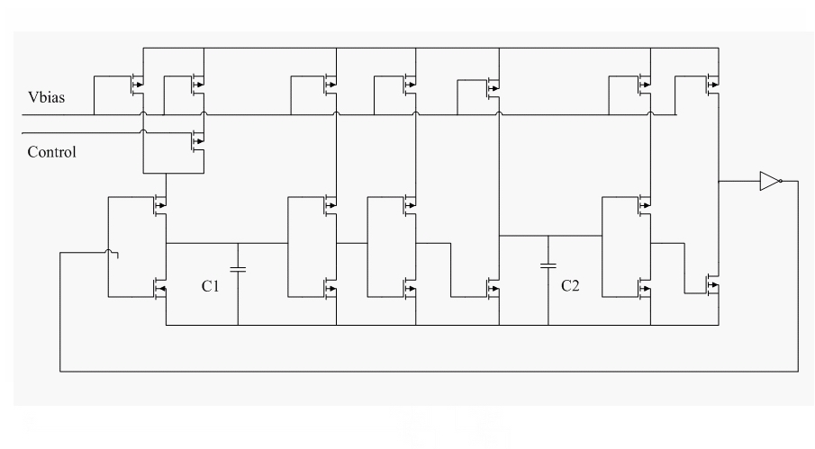
I'm designing a oscillator this days, but I do not know how to make the output frequency stable under diffrent libraries, such as SS, FF and TT. Its structure is very common: using mirrored current from reference to charge and discharge a PIP capacitor. The mirrored current will be diffrent under SS, FF and TT, and the value of capacitor will change too. As a result, the output frequency will change from 70k to 160k, it's a serious problem. I know trimming the current or the capacitor will make sense, but I see no trimming on the layout of many chips. How can they make the frenquency stable? Is there any method to solve the problem without trimming?