Continue to Site

Welcome to EDAboard.com

Welcome to our site! EDAboard.com is an international Electronics Discussion Forum focused on EDA software, circuits, schematics, books, theory, papers, asic, pld, 8051, DSP, Network, RF, Analog Design, PCB, Service Manuals... and a whole lot more! To participate you need to register. Registration is free. Click here to register now.

1Ghz Dipole in HFSS With Strange Results

Status
Not open for further replies.

ahmed osama

Full Member level 6
Joined
Jul 18, 2004
Messages
352
Helped
2
Reputation
4
Reaction score
0
Trophy points
1,296
Location
Cairo, Egypt, Egypt
Activity points
2,652
1Ghz Dipole in HFSS With Strange Results

so sorry i am new to hfss & EM Sim. in general ??

any one has idea why the rad. pattern is strange , it should be a do-nate around the z-axis
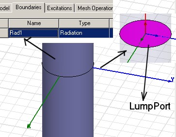
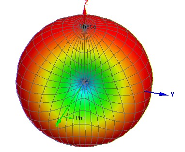
61_1159649114.jpg


81_1159649157.jpg


thx for ur time
 

I think that there is a problem with your port definition
consult the example below to see how to assign ports
 
m_uzman said:
I think that there is a problem with your port definition
consult the example below to see how to assign ports

can't download ur file can u plz send it to me

ahmed.osama @ gmail .com
 

m_uzman said:
I think that there is a problem with your port definition
consult the example below to see how to assign ports


it is so good , but it didn't say the dim. of the port so i can't get the same good result like its results??


any one else has extra tips for dipole antenna sim in HFSS or CST MICROWAVE STUDIO ????????????


thx all
 

ahmed osama hi,
you did a very good job in the design, why you want to switch to another software. you drawn a good model but the following notes will make your life easy and get the correct result, am still checking and I may modify the structure and post it sometime soon:
1- there is no material assignment for the dipole, assign it to pec (perfect electric conductor).
2- when you do that you will discover that the lumped port assigned is short, think it of a simple battery both of its port are connected to the same conductor.
to solve this problem move the above and below cylindrical by lets say +/-0.1 mm, and set a rectangular of vacuum to fill it along the z -axis and set the port at this rectangular.
3- I think that the radiation boundary is wrongly defined, normally you draw a box or in this case lets say a cylindrical that encapsulate the antenna with lambda/4 (based on the frequency used) distance from any part of the box, and then assign the radiation boundary to it .

keep the good work.

:D

Added after 1 hours 3 minutes:

this is the project file modified with a simulation, please after checking it and find the diferences between both yours and mine, redo the project from scratch to get the maximum benfit form it.
 

I also want to know how to model a dipole in HFSS. i haven't modeled sucessfully a good balanced input dipole. so could u pls send me the pdf file or HFSS project file to my email coz i do not have enough points to download it.

my email: ramanujancn@hotmail.com
 

hi,
sorry for the hude file that is inculuded in the above reply. it is the simulation and the result that is wht it is soooo big, included below is the model HFSS file only. hoping it is used ful.
 

Status
Not open for further replies.

Part and Inventory Search

Welcome to EDABoard.com

Sponsor

Back
Top