Continue to Site

Welcome to EDAboard.com

Welcome to our site! EDAboard.com is an international Electronics Discussion Forum focused on EDA software, circuits, schematics, books, theory, papers, asic, pld, 8051, DSP, Network, RF, Analog Design, PCB, Service Manuals... and a whole lot more! To participate you need to register. Registration is free. Click here to register now.

One way power flow within transformer with low pass filter

Salvador12

Full Member level 4
Joined
Jul 16, 2014
Messages
209
Helped
3
Reputation
6
Reaction score
7
Trophy points
1,298
Activity points
3,981
I will make a setup and i'm almost sure how it should work, but I want to check. Sorry for my previous threads being somewhat confusing.

So the idea is this. I have a high frequency generating coil part of a circuit and I need that high frequency to be converted down to mains frequency.
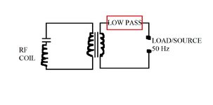
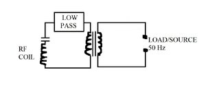
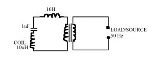
I will make the high frequency coil generate PWM wave into the primary of a transformer with a capacitor in series. So the primary loop as can be seen in the drawing is a series LC.
the secondary contains a low pass filter.
If my understanding is correct and please do correct it if necessary two things should happen

1) Power should be able to flow from the high frequency side through the transformer/filter into any load on the low frequency side
2) Power from the low frequency side (if load become source) cannot flow back into the high frequency side , at least not by any large margin because the frequency is low and the high frequency side has low capacitance capacitor + series LC resonance would present a very high reactance to the low frequency

Therefore due to differences in frequency power can only flow from left to right in the drawing and not vice versa or it can flow from high frequency side to low frequency side but not back, correct?

Another question is this, given the primary side and secondary side work on high frequency, the transformer therefore can also be a high frequency transformer , but as a high frequency transformer its turns ratio would be different than a typical mains transformer, yet the secondary side of the transformer still has mains 50 Hz across it, how would these factors work, because as far as I'm aware a low pass filter does permit low frequency power flow both ways right? It's only the high frequency that is cut off, so the low frequency power would be able to reach the transformer secondary ?
But if I'm right given the transformer primary works with high frequency and would present an almost open circuit for low frequency it would make the transformer secondary a very high inductance load for the 50Hz current so that would block the low frequency power from passing through the transformer. One thing i'm not sure is how would the low frequency power affect the secondary coil given it would have a lower turns ratio than a mains transformer and therefore would heat up with 50Hz current passing through it?
 

Attachments

  • ONE WAY POWER TRANSFER.jpg
    ONE WAY POWER TRANSFER.jpg
    47.2 KB · Views: 29
Hi,
I need that high frequency to be converted down to mains frequency.
Sure? A high frequency converted down to a low frequency?

***

A transformer always works both ways. (As long as it acts as a transformer). And a transformer always is lossy.
You have a voltage transformation and an inverse current transformation.

If you put HF (HF only, no LF) on the primary of a transformer .. then there will be HF only at the secondary.
Now if you put a LPF at the output ... it attentuates the HF ... and passes the non existing LF .. so, no HF and no LF .. means the output is about nothing.


Thus I hve to say your understanding is not correct.
There are free and easy to use circuit simulators. Just use them to see what happens to the signals.

***
Simple mind experiment:
You have a transformer. Lets say 230 V --> 12V.
now let the secondary OPEN and measure the primary current. It will be very low. Some milliAmperes.
Now draw 23A at the secondary side .... what happens? The current at the primary side also will increase. It will be about 1.2A.
Why because a transformer works in BOTH directions.
And it is always true: P_in = P_out (ignoring losses) means [V_in * I_in = V_out x I_out] ... independent of frequency
But the frequency will be the same. You can not expect to put in HF and the output will be LF.

In detail there will be losses, there will be (inductive) magnetizing current, there will be overtones.. But all this can´t ignore physics.

but as a high frequency transformer its turns ratio would be different than a typical mains transformer,
No. The RATIO will be the same.
230V : 12V will always will result in a turns ratio of 230:12 ... independent of frequency.

yet the secondary side of the transformer still has mains 50 Hz across it
No. There will only be 50Hz at the secondary if you put in 50Hz at the primary.

*****
I recommend to read about basic transformer operation.

Klaus
 
I fear the post continues the confusion brought up in this previous thread https://www.edaboard.com/threads/frequency-in-different-loops-joined-via-transformer.410522

It would be really helpful to see a complete principle schematic of the setup that clarifies what kind of conversion is addressed here. I can just guess that the topic is PWM. You have a high frequency carrier modulated with a low frequency signal, e.g. 50 Hz sine. You want to opearte the circuit as low frequency power source, e.g. an UPC or grid tied inverter.>

Frequency conversion is a non-linear operation, in a PWM output stage it's accomplished by switch transistors. The output of the PWM stage is mixture of high frequency carrier and generated low frequency signal. The signal path between PWM stage and output must be able to pass the low frequency component, e.g. the cut-off frequency of coupling capacitors must be below the low signal frequency, also a transformer must be designed to carry it, it's basically a 50 Hz transformer and not a "high frequency coil".
 
@KlausST and @FvM yes, pardon, I did get confused , sure a transformer always works both ways the field couples the current between coils. I do know that. I got mistaken in my schematic, what I did wish to make is a schematic where there is a loop with a coil in it that generates HF, but the loop also needs a filter element so that the transformer primary that is also part of the loop only has low frequency component across it.
This I think should be possible because even though the coil generates PWM at high frequency the loop which the coil is part of should filter out the HF part and leave only the 50 Hz signal behind which then is fed into the primary. I redesigned my simple schematic, am I closer or is this still wrong?
 

Attachments

  • ONE WAY POWER TRANSFER.jpg
    ONE WAY POWER TRANSFER.jpg
    46.4 KB · Views: 20
Hi,

so this is not "general PWM" but "SPWM". (you need to say this)
SPWM is low frequency sine modulated by with high frequency PWM.

If you want a sine, you just need the low pass filter. No extra transformer neded at all.

And exatly this is done billion times already. Nothing new so far.
So what exactly is the question/issue?

Btw: your LPF needs a third leg to the bottom line. Especially because the load impedance of the filter varies in a wide range.

Klaus
 
'PWM through a transformer': Scope traces make it apparent that the low frequency rises above and below a centerline. It can be carried by the PWM although the high frequencies are affected by transformer parameters.

Here the primary Henry value is adjusted (by user moving a slider) to a midway value which partially filters out the high frequency. This is theory (simulated) although it can give us a few insights in approaching this topic.
SPWM fm 2 opamps stepup xfmr resis load 1A (no filter).png


Link below opens my schematic above in Falstad's animated interactive simulator and runs on your computer:

tinyurl.com/2xsech2v

Enlarge scope trace region by dragging its border upward with mouse.
 
Hi,

so this is not "general PWM" but "SPWM". (you need to say this)
SPWM is low frequency sine modulated by with high frequency PWM.

If you want a sine, you just need the low pass filter. No extra transformer neded at all.

And exatly this is done billion times already. Nothing new so far.
So what exactly is the question/issue?

Btw: your LPF needs a third leg to the bottom line. Especially because the load impedance of the filter varies in a wide range.

Klaus
the transformer is there just for voltage step up, the main idea is for one way power flow. Normally 50 Hz or any other frequency flow through a transformer both ways but here the power comes from a coil generating as you said SPWM which I understand is just a better way of doing PWM for a fixed frequency sine wave to result in less harmonics right? So essentially due to the high frequency high inductance primary loop, power can only flow from the high frequency side into the low frequency side but whatever power is at the low frequency side cannot flow back into the high frequency generating loop due to it having a high reactance blocking practically all low frequency current down to very low value
 
the transformer is there just for voltage step up,
so a quite usual low frequency transformer?
Normally 50 Hz or any other frequency flow through a transformer both ways
Same is here.
a better way of doing PWM for a fixed frequency sine wave
I don´t know what "fixed frequency sine wave" means.

So essentially due to the high frequency high inductance primary loop, power can only flow from the high frequency side into the low frequency side
Power flow is form source to load.
If source is on the left side and load on the right side power flow is from left to right.
If source is on the right side and load on the left side power flow is from right to left.
The transformer does not care.

Even if source side is on the left side and load is on the right side, then right side current (load current) will be transformed back to the left side. All standard transformer operation.

low frequency side cannot flow back into the high frequency
The only part that really is frequency dependent is the filter, not the transformer. (for it´s operation principle)

having a high reactance blocking practically all low frequency current down to very low value
If there is a "blocking part" then it acts both ways.
What part is the mystic "high reactance blocking part"?
The series capacitor? If so, then it blocks low frequency power/voltage flowing from left to right in first place.No voltage, no current.

You always need to see the voltage for a dedicated frequency and the current for the same frequency.
Again: there is no "frequency conversion" (at least not in your circuit).
There is nothing that converts HF to LF.
The LPF works this way: IN: (HF + LF) --> LPF --> (LF only). No HF forward, no HF back. No energy conversion from HF to LF.

*****
Do you understand this:
The source pushes voltage to the load. The load impedance causes current to flow. This current will "flow" back somehow to the source.
Current times voltage is power.

****
We are running in circles. Do your research. Draw more detailed sketches. Draw waveforms. Maybe draw the spectrum diagrams. Show scope pictures or at least how you expect them. Show formula, show math. Give us something we can validate.

I won´t go on with this lengthy and ambiguous texts.

Klaus
 
You are describing the functions of all AC sine inverters. The transformers are always reciprocal. But the switches are not. This may used in an ac-dc-ac UPS.

Search for clues on the web for design block diagrams and schematics.
 
I have a simulation comparing all possible arrangements of AC supply through transformer, with:
* rapid switching on either primary or secondary
* small inductor on either primary or secondary.

The purpose was to observe if a configuration if better at filtering out high frequency to the load, as well as efficiency to drive the load with mains frequency. This would need real-life experiments to discover whether simulated theory is in accord with real life.

Circuit A is straightforward switched at 80% duty cycle.
Circuit D does the smoothest filtering job but also has large power factor error.

compare 5 layouts transfomrer (w PWM n inductor) 50 Hz  .png


Link:
1) Opens animated interactive simulator at falstad.com/circuit
2) Loads my simulation,
3) Runs it on your computer.

tinyurl.com/25ygvdoe

Toggle full screen (under File menu).
Enlarge scope traces by dragging scope region upward with mouse.
 
The "one way power flow" or "low frequency current blocking" concept doesn't work, as already stated by others, except for the purely theoretical idea of making a high impedance AC current source. Practical inverters are either voltage sources or current sources with very limited impedance, e.g. Z-source inverters.

One way power flow of a converter has to be achieved by controller design, generally speaking by setting the converter AC voltage so that the output current has intended phase and magnitude.
--- Updated ---

A simple time-continuous equivalent circuit is comprised of converter output voltage, grid e.m.f. and a connection impedance, the sum of grid impedance and converter output impedance. The connection impedance is mostly inductive, current is set by controlling the voltage drop along the connection impedance.
 
Last edited:
The "one way power flow" or "low frequency current blocking" concept doesn't work, as already stated by others, except for the purely theoretical idea of making a high impedance AC current source. Practical inverters are either voltage sources or current sources with very limited impedance, e.g. Z-source inverters.

One way power flow of a converter has to be achieved by controller design, generally speaking by setting the converter AC voltage so that the output current has intended phase and magnitude.
--- Updated ---

A simple time-continuous equivalent circuit is comprised of converter output voltage, grid e.m.f. and a connection impedance, the sum of grid impedance and converter output impedance. The connection impedance is mostly inductive, current is set by controlling the voltage drop along the connection impedance.
Why purely theoretical? Apart from some possible misconception on my part on where to best put the LPF, otherwise I believe what I showed in my drawings is a high impedance AC current source. The left side coil generates high frequency PWM square wave that then after filtering leaves only the 50 Hz low frequency. The left side coil might be of low impedance itself as it is a high frequency coil with only a few turns, but the series capacitor is also of low capacitance. 50 Hz power through a 1uF capacitor for example would be limited to mA at best. So what did I say wrong when I stated that this has to be a "one way" power flow schematic. The power realistically can only flow from the high frequency side to low frequency side because the low frequency will experience a high impedance load if it tries to pass through the left side coil and capacitor forming a series LC.
 
The power realistically can only flow from the high frequency side to low frequency side because the low frequency will experience a high impedance load if it tries to pass through the left side coil and capacitor forming a series LC.
You are analyzing a fictive circuit not a real converter. I conclude that you didn't understand the explanations given in the above discussion. Specifically there's no way to block low frequency reverse power flow by a filter or blocking capacitor, it would also block forward power flow.

Your posts don't yet show a way to implement a high impedance AC source.
Also @KlausST Ok. I get it, the 50Hz would be present on the primary loop on the left side , although not much would get through the series capacitor due to it's high reactance.
Are you saying that the low frequency component of the PWM signal would not be able to properly get through the capacitor for the same reason the low frequency 50 Hz current won't get through? So the series capacitor due to its low capacitance - high reactance would just allow the PWM carrier to pass through and effectively attenuate the low frequency component therefore making the use of PWM useless.
 
Last edited:
Can you show principle diagram of the intended circuit, showing at least pwm switches up to output terminals?
The switches are not within this diagram. The coil on the left side loop is a generating coil, current is induced in the coil. You can disregard the LPF block for reasons already discussed here.
But i understood my thinking error. I cannot induce a PWM signal with 50 Hz component within the left side generating coil because the capacitor due to its high reactance will attenuate the low frequency to very high extent.

I think a much more realistic solution would be to simply use 50Hz sine in the generating coil and use a larger inductor in series with the capacitor to achieve resonance in the series LC, so essentially an inductor in series with the transformer primary, please see the changed attached drawing.
PS. I added approximate values to the coils that would match to resonance.
Factoring in the transformer primary inductance which would change with load , the total value of all coils should be made such that resonance of the whole primary loop is when the transformer load is highest which would be logical as then maximum energy would need to flow, and the loop moving slightly off resonance with decreasing load on transformer.
 

Attachments

  • ONE WAY POWER TRANSFER.jpg
    ONE WAY POWER TRANSFER.jpg
    45.9 KB · Views: 3
Hi,
the whole primary loop is when the transformer load is highest
Load = R (usable power)
Resonance = LC.
Do you notice there is no "R" involved in resonance.

Indeed R is somehow the opposite of resonance.
It rather kills a resonance. In the meaning of: on a resosnce case you usually get high voltage .. if you add an R usually the voltage becomes lower. Independent whether the R is in series or in parallel.

For sure one can use resonance to (optimize) transfer power from A to B. But from your description I can´t see how.

Klaus
 

LaTeX Commands Quick-Menu:

Similar threads

Part and Inventory Search

Welcome to EDABoard.com

Sponsor

Back
Top