Continue to Site

Welcome to EDAboard.com

Welcome to our site! EDAboard.com is an international Electronics Discussion Forum focused on EDA software, circuits, schematics, books, theory, papers, asic, pld, 8051, DSP, Network, RF, Analog Design, PCB, Service Manuals... and a whole lot more! To participate you need to register. Registration is free. Click here to register now.

Need experienced Circuit designer for project, want back and forth interaction

Spiffdandy

Newbie level 4
Newbie level 4
Joined
Apr 13, 2024
Messages
7
Helped
0
Reputation
0
Reaction score
0
Trophy points
1
Activity points
57
I am looking to add a small bank of super capacitors to my Etrike, not to provide power, but to be charged from the batteries to give a power boost when needed. It is a 60V - 1000 W motor. I need to put a diode between the controller and the motor to prevent backflow of capacitor surge in to the controller.
So Im needing:

diagram.jpg


Selection of capacitors ( voltage 80w? 100w?) *looking for 3-10 seconds discharge time at the desired voltage
Selection of Diode ( and any installation hints I might need to know)
Look at the diagram, anything else that I might need to include or change.

Thanks in advance
 
Hi Supercap banks need balancing, and management due to C+/-20% and this usually means the project is deemed too expensive and large.
 
Yes good point, you need to put a scope probe on the battery terminals, and do a sample and hold when you do the boosted power thing...see if the voltage dips.
If it doesnt, then the cap bank wont have any effect.
The drive to the motor may also have a hard current limit, so you cant draw the boosted power that you want anyway.
 
Tentative theory (simulated):
15 Farads appears suitable. It might last for ten seconds giving 1000 W initially, declining to 700 W.
Current draw is over 16A therefore it should be a gang of capacitors in parallel, say each carrying an Ampere. Each wire should be sized large enough to carry its share of current.
22 gauge for 1 Amp.
10 gauge for 17 Amps.

My simulation shows a capacitor alone providing power. Not shown is the battery pack.

supercap 15F 60VDC sends 1000W declines in 10 sec.png
 
That only will help if the battery voltage significantly drops under heavy load.
Have you determined that it does?
It shouldnt matter as the Caps will have a voltage charge, 20-40 volts higher than the battery voltage and feed to the motor only, which is why I need to isolate it from the controller. *There are you tube vids out there that show using a Super Cap bank instead of a battery to start a motor. Thats the kind of power Im looking for, but need specifics on how to set it up for my 60 volt config. as a booster.
--- Updated ---

Tentative theory (simulated):
15 Farads appears suitable. It might last for ten seconds giving 1000 W initially, declining to 700 W.
Current draw is over 16A therefore it should be a gang of capacitors in parallel, say each carrying an Ampere. Each wire should be sized large enough to carry its share of current.
22 gauge for 1 Amp.
10 gauge for 17 Amps.

My simulation shows a capacitor alone providing power. Not shown is the battery pack.

View attachment 190074
Thanks for this awesome input. Any ideas on Diode selection .... *tips for installation?
 
it shouldnt matter as the Caps will have a voltage charge, 20-40 volts higher than the battery voltage and feed to the motor only
Do you mean you are going to put the 60+(20V) across the "drive and motor"...the motor must surely be a BLDC, and so you cannot just put voltage on it...the voltage has to go through an inverter drive, then to the motor.

So , as far as it looks to now.....you are feeding a BLDC inverter with 60V...and lets say it is dropping out when you want higher power, so you then switch in an 80V supercap bank? Though that will mean an awful high inrush current which could blow whatever switches you are using between the supercaps and the drive's DC input bus.

If and only if the batt is dropping out, you could switch in extra storeage via some kind of current limited switching converter. But you wouldnt need to switch the battery out.
 
Last edited:
Thanks for this awesome input. Any ideas on Diode selection .... *tips for installation?
Ebike circuitry starts to border on automobile specs. The diodes I once saw installed in our car alternator were 'top hat' shape, something like 50 Ampere rated. The mechanic pounded the old ones through holes in a heat sink and pounded in the new ones.

2 Watts is expected heat dissipation in your case as a diode carries 17 Amperes. Depending on length and frequency of use you might only need minor heat sinking.

If your battery pack is declining, then trying to draw that much more power from it shortens a charge. Maybe you can manage in that case. (I would want to try to extract as much power as the batteries hold).

Now the idea of adding 'a few volts' to battery voltage implies a revision in your goal, to add a boost or buck-boost converter.

An Ebike store would want to sell you new and more powerful batteries, but they also might have advice about modifying your present hookup, because it's taking a chance of doing something wrong.
The battery is actually fine. During a fast acceleration take off, or a take off with heavier load, the amp draw goes way up and the battery shows less available power for those few seconds. What Im trying to do is likened to hitting the nitrous switch on an ICE engine, extra power for a short burst. Any ideas on how I can better achieve this is welcome and appreciated.
 
You could put a voltage sensor on the main battery...then when it drops in voltage as you draw extra power.....
One way may be to have a second battery of some 100V or so....then when the voltage sensor reports low battery volts on the main batt,
(becuase of the extra current being drawn)
you get an
ON/OFF controlled buck converter (output current controlled) to shovel say 20Amps into the main battery output bus.
It would have to clamp at 20A (or whatever is appropriate), and obviously not overvoltage the main batt.
It must be clamped to the Amp ratings of your circuit otherwise it'll smoke.
On/off controlled because this is cheap, simple, and can respond instantly to the need for extra power...and wont overshoot in its
current delivery.
 
You can keep a capacitor charged from the battery during normal running, then reverse its connection so its voltage adds to a drooping supply voltage. The extreme load receives a 'boost' just when it needs it. To do this you press a switch at a critical moment of your choosing.

10 F might yield a ten second 'boost' if you add the drooping battery voltage. You must let up the switch after those few seconds. After the battery resumes normal running voltage, it takes a minute for the cap to charge back up.

capacitor 10F adds about 40V to 30V supply for crisis (switched).png
 
You could put a voltage sensor on the main battery...then when it drops in voltage as you draw extra power.....
One way may be to have a second battery of some 100V or so....then when the voltage sensor reports low battery volts on the main batt,
(becuase of the extra current being drawn)
you get an
ON/OFF controlled buck converter (output current controlled) to shovel say 20Amps into the main battery output bus.
It would have to clamp at 20A (or whatever is appropriate), and obviously not overvoltage the main batt.
It must be clamped to the Amp ratings of your circuit otherwise it'll smoke.
On/off controlled because this is cheap, simple, and can respond instantly to the need for extra power...and wont overshoot in its
current delivery.
You have the idea. Im kind of following what you are saying. Any chance of a one line drawing for what you explained? Thanks a ton !
 
You can keep a capacitor charged from the battery during normal running, then reverse its connection so its voltage adds to a drooping supply voltage. The extreme load receives a 'boost' just when it needs it. To do this you press a switch at a critical moment of your choosing.

10 F might yield a ten second 'boost' if you add the drooping battery voltage. You must let up the switch after those few seconds. After the battery resumes normal running voltage, it takes a minute for the cap to charge back up.

View attachment 190092
If Im reading your drawing correctly, what you are showing is a voltage sensor seeing the 30V and switching automatically, or is that a manual switch situation. The 7 and the 3.6 are resistance values? Forgive my ignorance. Also, would a shotsky (sp?) Diode be the best fit for this?
 
Do you understand motor torque depends on motor Rs [ohms] and applied voltage from source with ESR [ohms] such that I= Vbat/ {Rs+ESR} ?

All batteries may be modelled as a massive capacitor array with an equivalent C and series resistance ESR, with many cells in series/parallel. (computed from Ah and C-rating for ESR with V and S-P array of cells. Capacitance C is the charge Q/V=C and C-rating refers to current multiplier of Ah which is limited by temp rise of ESR of cell array.

A Supercap may have lower ESR but far lower capacitance even if it is 10 Farads compared to one cell = 10 kF
So your turboboost might last a less << 1 second. Let's find out.

The capacitance equation with torque proportional to current is Ic=C dV/dt +(Vbat-Ibat*ESR*-VBEMF)/DCR.
As the motor speeds up it creates Back EMF (VBEMF) which drops the winding current along with torque.
DCR is the BLDC motor DC coil resistance for each coil in parallel.

So even if you have say 20 cells in series for 72V and (?) in parallel, the capacity, C reduces by N=20 but the voltage increases (x20) and ESR of each cell adds by N*ESR cells. e.g. 80 mohms*20=1.6 ohms while the Supercap might be in milliohms so the discharge rate is limited by the load R.

Let's look at time constants top reach 63% of max speed for Tau= RC
If this was 5 seconds with 10 kF/20 = 500 Farads, your body load acts as R and Rload=T/C=5s/500F = 10 mohms
Thus, if the supercap = 5F, T=RC = 10 mohms * 5F = 50 milliseconds
This
is how long your Turbo boost will last!

But they don't make 72V Supercaps in 5F, so it is not feasible to gang them, as they are expensive, and they need a BMS for mismatched protection.

Your best bet is to add 20 cells in parallel. (assuming I guessed correctly) You can copy my formulae and subst. you actual values.

Any questions?

The motor equivalent R at max power is only 10% of surge start power and current..
1000 W @ 60V (not 72) P=V^2/R , Rload = V^2/P= 3.6 Ohms so I doubt my Rload for start of 10 mohms is accurate and should be more like 10% of 3.6 ohms or 360 mohms. What if your 63% time was 10 s ? 20 s?
 
Last edited:
You can keep a capacitor charged from the battery during normal running, then reverse its connection so its voltage adds to a drooping supply voltage. The extreme load receives a 'boost' just when it needs it. To do this you press a switch at a critical moment of your choosing.

10 F might yield a ten second 'boost' if you add the drooping battery voltage. You must let up the switch after those few seconds. After the battery resumes normal running voltage, it takes a minute for the cap to charge back up.

View attachment 190092
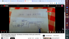
OK I found this on a you tube video (not my drawing) . This would simplify alot, although I do like your drawing. In this case the caps always go thru the controller, in which case I would need to match the cap voltage to 60v (60-66% range). Most 10F super caps are 2.7v so I would need to series 23 caps together. If I do series them, the output is still 10 F ? is that correct ? Do you think this will work ?diagram 2.png
 
In theory the idea looked good on paper. However roadblocks pop up around every corner. To operate the project requires manual switching (for a while as you experiment with automatic sensing and switching). You must watch electrical readings most all the time.

You might get it to work if money is no object. The supercapacitors need to convey upwards of 20A. It takes more than one string. And there's a caution concerning capacitors in series: They're prone to imbalance. One of them might adopt 1V, another 5V which ruins it. There are industries assembling massive gangs of these supercaps, yet I keep wondering, how long does it stay new? Among hundreds of caps, how do you track down a bad one?

And seeing Tony's post #15 above it's hard to argue with the figures he brings up.
 
How long does it take you to reach full speed? What was it new?
What would do you need it to be? In seconds.
I takes about 10 seconds to reach full speed. However, the Amp draw is high on a fast take off (sometimes a fast take off is safer for entering busy traffic) and the batt charge meter will drop from 100 to 25% if I max the throttle from a full stop. It recovers after about 10 seconds of letting off. A few times I have had the breaker trip after running it for a while (30 mins plus) then doing a fast take-off. I would be looking for the Cap bank to take the load for the first 5 - 10 seconds to smooth out the draw from the battery.
 

LaTeX Commands Quick-Menu:

Similar threads

Part and Inventory Search

Welcome to EDABoard.com

Sponsor

Back
Top