Continue to Site

Welcome to EDAboard.com

Welcome to our site! EDAboard.com is an international Electronics Discussion Forum focused on EDA software, circuits, schematics, books, theory, papers, asic, pld, 8051, DSP, Network, RF, Analog Design, PCB, Service Manuals... and a whole lot more! To participate you need to register. Registration is free. Click here to register now.

Most noise free way to carry high speed serial bit streams

Status
Not open for further replies.

cupoftea

Advanced Member level 5
Joined
Jun 13, 2021
Messages
2,602
Helped
54
Reputation
108
Reaction score
115
Trophy points
63
Activity points
13,641
Hi,
Is the attached differential signalling?
Does it need 4 wires or 3, or 2?
...ie , just the two signal wires, or each signal wire twisted with ground, ie 4 wire.

LTspice and jpeg attached

Differential signalling_.jpg
 

Attachments

  • Differential signalling_.zip
    1.9 KB · Views: 120

With balanced signaling there should be no return
current. RS-422 has a balance spec for the difference
voltage in the two states, to make that so (or nearly).

The discussion ought to first declare what "high speed"
means. RS-422 could be anywhere from 10MHz short
haul to tens of kHz, if I recall, at km distance (my RS-422
chip designs were back in the late '80s, it's getting a bit
foggy). Anything faster will operate at lower voltage so
lesser noise immunity, but what do you really need?

You'll be way ahead on "time wasted in discussing over
and over" if you pick a legit standard and avoid making
a bodge that then must be reviewed by anyone or
everyone. If you tell them RS-422 they will nod their heads
up and down and move on.
 
100% in agreement with Dick_freebird on this one.

Looking back to your original post, you have a microcontroller producing the signal so I'm guessing we are talking about relatively slow signals, your driver also suggests it isn't particularly fast. You then pass it along unterminated wires to buffers for no apparent reason then reverse the operation performed in the microcontroller by inverting one signal and adding it to the other. Finally, you level shift the output to convert it back to microcontroller logic levels.

All of this seems over-complicated and almost designed to make performance worse. If you use a simple 8-pin RS422 transceiver it will take logic levels in, give logic levels out and do all the differential work in the middle for you. The most you need is a single resistor to terminate the differential wires and in most cases even that can be left out. You can also get slew rate limited drivers to further minimize signal radiation.

some useful info here:
note that when it mentions a four wire system it refers to two wires for transmitting and two for receiving, if you are only sending you only need two wires.

Brian.
 
Looking back to your original post, you have a microcontroller producing the signal so I'm guessing we are talking about relatively slow signals, your driver also suggests it isn't particularly fast. You then pass it along unterminated wires to buffers for no apparent reason then reverse the operation performed in the microcontroller by inverting one signal and adding it to the other. Finally, you level shift the output to convert it back to microcontroller logic levels.
...Yes my apologies, that was my first effort...the better effort is in post hash18.
 

Hi,

I agree with the others.

why putting some "better effort" that makes the the situation worse? I see no benefit.

--> I´d go with RS422/RS485 (or other digital differentialinterfaces)

Klaus
 
...Yes my apologies, that was my first effort...the better effort is in post hash18.
Better than what? You continue to ignore the reality of what differential signaling is, actually going as far as showing signals that are NOT differential in an attempt to “prove” that differential signals need a ground.

I’m done.
 
Thanks, AYK, a differential sigbak, is comprised of two signals, which are the opposite of each other....ie, one is high when one is low, and vice versa. The signal received is the subtraction of the two signals. Thats whats shown in the above post of hash18
 

You continue to ignore the reality of what differential signaling is, actually going as far as showing signals that are NOT differential in an attempt to “prove” that differential signals need a ground.
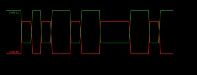
Thanks, so it is believe that the attached is a differential signal? That is, the high and low states are equidistant from the centre voltage of the rail to rail voltage (Vcc).

..I think in most systems, the ground potential at the RX will be different than at the TX, so the signals may be equidistant at the Tx, but wont be at the Rx.....so in such a case, i presume you would say that the differential signal is not differential at the Rx?


...it all seems a bit ramshackle.......supposing i have a Tx Vcc of 5V, and my diff signals are 3V for Hi, and 2V for low (as the "should" be)......are we really saying that if i keep it like that, but raise my rail voltage to 6V, then all of a sudden , its not a differential signal any more?
All seems a bit "wet finger in the air".

Te Rx circuit hasnt got a clue what was the Vcc of the Tx circuit......

What if Vcc at Tx is 5V, and Vcc at Rx is 6V......then its impossible to have differential signalling between them?
__---___
The following gives the definition of a Differential signal, and its exactly what i show above, in post #18.
--- Updated ---

The below article on differential signalling...
...states that...
"Contrary to popular belief, differential signalling does not affect noise cancellation."

This is contrary to the following article from Altium..

The article from Altium appears to be interchanging its reference to balanced differential signalling, and plain "differential signalling".

"Balanced differential signalling" (BDS) appears, in most articles, to be the one that results in most noise cancellation.......BDS specifically involves two signals which are opposite in polarity , and equidistant from the zero voltage reference........but in most comms systems...the zero voltage reference is at different potentials at each end of the comms cable.....so what that means for BDS is anyones guess...presumably its not balanced any more, and you will get a lower SNR?

A simple scheme like what i show in post #18 will obviosuly result in a reduction in common mode noise, since obviously, noise of the sme polarity on the comparator inputs will be cancelled......so what the nae is, of the comms scheme that i show in #18, goodness only knows.

Searching the web for official articles, reveals a wide variation about what "differential signalling" is, and what it actually does.

The method of signalling in CAN (attached) is NOT "differential signalling" according to many articles.
 

Attachments

  • Differential signal.jpg
    Differential signal.jpg
    59.6 KB · Views: 95
Last edited:

You are completely missing the point. Differential signalling does not mean the signals are equidistant from ground, if fact quite the opposite, it allows them to be at any reasonable potential. It is the voltage BETWEEN THE DIFFERENTIAL WIRES that matters, those are the signals that are inverts of each other. Both can be lifted above or below ground, the important thing is they should be as close to each other in amplitude and should change state at the same time.

Standard line differential drivers have been around for decades, they take a single logic level input, give a single logic output and do all the inverting, impedance matching and protection internally.

Brian.
 
Standard line differential drivers have been around for decades, they take a single logic level input, give a single logic output and do all the inverting, impedance matching and protection internally.
Thanks,...in systems where there are loads of PCBs and comms between them....there are loads of comms and noise problems, and its useful therefore, to get into the comms protocol, and find out what its about, so that you can correct it......the LTspice sim of #18 is all about trying to get into it.

You are completely missing the point. Differential signalling does not mean the signals are equidistant from ground, if fact quite the opposite, it allows them to be at any reasonable potential. It is the voltage BETWEEN THE DIFFERENTIAL WIRES that matters, those are the signals that are inverts of each other. Both can be lifted above or below ground, the important thing is they should be as close to each other in amplitude and should change state at the same time....
Thanks, in that case, according to your kindly supplied definition, the LTspice sim i posted in post #18 above, involves differential signalling. (But In post #25 it was declared that this was not differential signalling.)
 

Thanks,...in systems where there are loads of PCBs and comms between them....there are loads of comms and noise problems, and its useful therefore, to get into the comms protocol, and find out what its about, so that you can correct it......the LTspice sim of #18 is all about trying to get into it.


Thanks, in that case, according to your kindly supplied definition, the LTspice sim i posted in post #18 above, involves differential signalling. (But In post #25 it was declared that this was not differential signalling.)
You are just willfully ignorant. The signals in post 18 ARE NOT DIFFERENTIAL.
 
You are just willfully ignorant. The signals in post 18 ARE NOT DIFFERENTIAL.
Thanks, a true and absolute definition of "a differnetial signal", does not appear to exist anywhere on the web.
Hours of searching show this.

What we can say, is that the "configuration of signals" shown in the LTspice simulation of post #18, gives some noise reduction by way of the fact that the signal seen at the Rx end comparator is bigger than a single ended signal which is simply compared to a reference voltage of midrail potential.

I agree that there are times when both signals are at ground potential, but that is harmless, and the signal is not "read" durring those times anyway.

Some texts say that a differential signal must have equal impedance between each other and between themselves and ground and rail, but many articles do not specify that as a stipulation for "differential signal".

In most articles, a "differential signal" is simply stated as being two signals which at any time, are opposite to each other...ie, one is logic high when the other is logic low, and vice versa. That is indeed what i have in the LTspice sim of post #18.

There is one text which states that the differential signals if sent from a 0-5V Tx, must be equidistant from the midrail voltage (ie 2.5V)...but only one article states that.

_______--------_______--------_______-------
Like many, we are not actually interested in what a signal (or diff signals) are called, but how noise free they make the comms link...the things that make the comms link noisy are as follows....

1...High di/dt in the signalling current
2....High dv/dt in the signal voltages
3...Wide current loop area of the signal wires
4...Small voltage difference between the wires that go into the Rx comparator's inputs.
5...common mode noise at the Rx input.
6....Noise sources near the comms cable
7...Signal reflections

1....is improved by slew rate limiting the current signals
2.....is improved by slew rate limiting the voltage signals
3.....is improved by use of twisted pair or coaxial cable
4.....is improved by having "signals that are sent as logical opposites of each other"
5....is improved by having a Rx comparator which subtracts the common mode noise at each input, which all comparators do (it cancels the CM noise, because its the same polarity at each comparator input)
6....is improved by Routing the comms cable away from noisy sources (eg SMPS switching nodes)
7...improved by termination resistors

So what is it, that "differential signalling" is needed for.
 
Last edited:

I don’t know where youre searching, but there are plenty of places that explain simply what a differential signal is, aside from the people here who are foolishly trying to explain it to you.

I can explain it to you, but I can’t understand it for you.
 
What we can say, is that the "configuration of signals" shown in the LTspice simulation of post #18, gives some noise reduction by way of the fact that the signal seen at the Rx end comparator is bigger than a single ended signal which is simply compared to a reference voltage of midrail potential.
Post #18 is NOT differential. It may have two signal paths but twisting each signal wire with ground is plain wrong. The idea is that twisting them around each other exposes them to near identical conditions so any interference is picked up equally and cancelled in the summing circuit. It also ensures equal length and impedance. For it to work at all in your circuit, the source MCU has to produce two identical but inverted signals, a conventional line driver does the inversion for you.

I agree that there are times when both signals are at ground potential, but that is harmless, and the signal is not "read" durring those times anyway.
How do you know this unless another signal is also sent to synchronize sending and receiving?

If you need to propagate a signal to several boards (typically up to 32) you connect all the receivers in parallel and terminate at the final one. If you need full duplex use RS422 devices and if you want half duplex (receiving data back along the same two wires) use RS485 and terminate at both ends and use pull-up and pull-down resistors on the lines if they can become tri-stated.

Simples...

Brian.
 
Post #18 is NOT differential. It may have two signal paths but twisting each signal wire with ground is plain wrong.
Thanks, are you saying that if i take LTspice of post #18, and just send the two signals, twisted with each other, and no ground, then , are you saying it becomes a differential signal?

When diff sigs are sent on a PCB, eg DDR, as you know, the two sigs go closely together, over a ground plane...its not just the two signals.
 

Hi,

I appreciate the patience of the posters.
I'm not that patient, if someone refuses to accept my posts then I guess he/she simply does not want to.

Now at post#35..
I still can just support them.
Differential signals are never meant to have the same level (like: buth LOW like in post#18).
They are designed to
* operate inverted with minimized time delay.
* when the one ins LOW, the other is HIGH
* when the one starts to rise, the other starts to fall
* rise time should be equal to fall time
* neither rise time nor fall time is extremely short. Not square wave, but trapezoid shaped.
.. they are designed to be symmetrical in timing, thus - for example - you can't just add an inverter to get the composite signal.
This all leads to the GND current to be minimized. Considered to be zero.

But still they may need a GND signal. (May need, not must need!) RS422/RS485 receivers need a GND to ensure the common mode input voltage range.
The each RS4xx signal is generated to be in the range of 0..5V (receiver side). RS4xx must tolerate a common mode shift (maye caused by a shift between transmitter_GND to receiver_GND) of additional +/-7V. Thus the RS4xx absolute input voltage range (each input) needs to operate -7V ... +12V.

If you disconnect GND of a RS4xx system .. the signal may float, thus you can't guarantee the input voltage to be within -7 ... +12V.
But in a RS4xx system GND is not needed for the function of "differential signalling".
If you have a DC free signaling using RS4xx for example (manchester encoded, for example, to avoid transformer saturation) you may use transformers to isolate the signals. You may then also isolate the GNDs. (You need some resistor network at the receiver side to "set" common mode voltage.
This is an example where RS4xx signal need no GND at all. You may use a simple wisted pair. 2 wires (and a transformer)

Now you cone with some "speciality" diffeent signalling: DDR signals on a PCB.
Technically the DDR signal may be operable without GND plane. But if the PDK tells you to use a GND plane ... then it's a good idea to follow the rules.
If you are interested in DDR signalling then I recommend to read deeple why the chose to use the GND plane. Possible reasons: multiple pairs, reducing EMI, simpler impedance control ..
But tbh I guess picking the DDR was just to argument with a "special situation" that the "general situation" is wrong. If so, it's no good idea for a technical discussion, it just annoys the partners.

Klaus
 
Status
Not open for further replies.

Similar threads

Part and Inventory Search

Welcome to EDABoard.com

Sponsor

Back
Top