Continue to Site

Welcome to EDAboard.com

Welcome to our site! EDAboard.com is an international Electronics Discussion Forum focused on EDA software, circuits, schematics, books, theory, papers, asic, pld, 8051, DSP, Network, RF, Analog Design, PCB, Service Manuals... and a whole lot more! To participate you need to register. Registration is free. Click here to register now.

VOUT overshoot reduction in SMPS?

Status
Not open for further replies.

cupoftea

Advanced Member level 5
Joined
Jun 13, 2021
Messages
2,589
Helped
54
Reputation
108
Reaction score
115
Trophy points
63
Activity points
13,604
Hi,
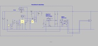
Would you agree, the attached is the De Facto method of eradicating overshoot in SMPS’s? As you know, opto-coupled SMPS’s have a slow bandwidth, and tend to suffer vout overshoot as a result. The attached is the best way to get rid of this, would you agree?
Simply using a 2nd error amp, set for a slightly higher vout than nominal, and with a slow start network, which of course, is "out of circuit", after whatever transient occurred has finished.

LTspice and jpeg attached.
 

Attachments

  • Overshoot reduction.jpg
    Overshoot reduction.jpg
    136.7 KB · Views: 111
  • Overshoot reduction.zip
    3.2 KB · Views: 94

Thanks, the second error amplifier has a very fast response, and can thus clamp the vout quickly in spite of using the same opto....(it only acts during the actual transient)...its actually slightly unstable, but it doesnt matter as it gets bypassed during non-transient operation.
 

Thanks, the second error amplifier has a very fast response, and can thus clamp the vout quickly in spite of using the same opto....(it only acts during the actual transient)...its actually slightly unstable, but it doesnt matter as it gets bypassed during non-transient operation.
But if the Opto Bandwith is the problem what use a a fast amplifier? I see your error amplifier is configured more like a PID controller, is that necessary? How have you tuned your control loop? Just wondering if your overshoot is in part due to the PID
 
Last edited:
But if the Opto Bandwith is the problem what use a a fast amplifier? I see your error amplifier is configured more like a PID controller, is that necessary? How have you tuned your control loop? Just wondering if your overshoot is in part due to the PID
These are great questions and at the heart of the matter.
Can't use a faster opto....digikey doesnt let you search on the parameters which pertain to speed of such an optocoupler. That is , the base_collector capacitance of the opto.....and in fat, only opto's with a 5V VCC pin are faster.....but most of them are "digital" opto's, and totally unsuitable.
Also, you cant use a faster bandwidth for the opto feedback loop, the opto simply wont let you.....you need "extra means" to stop overshoot happening.
Cant use a comparator either...as it will just result in system oscillation...the only way is the 2nd error amp that you see here.
How do you know your opto is the source of the overshoot? You have a pretty complex feedback network going on which could well be a major contributer to overshoot due to its PID nature. How do you know the control loop topology is the correct one and the values are correct?
 
I see your point, but please ignore the specifics of the sim attached....AYK, its well known that opto based feedback loops are much slower than direct divider feedback.

Another point, is that opto based isolation is useful when remote sensing is done, as well as when isolation is needed. AYK, in remote sensing if you dont opto isolate, then your entire control circuitry needs to be using a separate ground than the power ground, which can be a nuisance....whereas if you opto -isolate, then not all of the control circuitry needs to be separate from power and power ground, which is a big relief.
 

Well as you say, SS function overriding the main loop is
a done thing and one reason may be output overshoot
(there are others).

But "applying the parking brake while driving" may not
be the best idea or even practical. You'd have to discern
that an unacceptable transient was occurring, in time to
do something about, and then quit messing in time to
prevent the opposite problem.

In space applications of "classic PWMs" this (SS false
trigger) is near the top of the power integrity ways-to-fail
list (power cycling random sections of a bird, with stupid
long recovery time).

Now maybe you should ask yourself what would actually
cause such an output transient, how, and whether some
other mitigation (VIN clamp? "Heavier" loop filter?) holds
more promise / less "icky poo".
 
Playing with the simulation I eliminated the startup overshoot by adding a 2k ohm resistor in series with the U1 COMP output (below) without the Overshoot Reduction Amp connected.
Don't know how much that will affect the loop stability however, but it seemed stable when I added an output transient load.

I don't think the response time of the opto has anything to do with the overshoot as its response time is much faster than then feedback loop compensation time-constants.
It's likely caused by saturation in the feedback loop (integrator windup) during startup, and the overshoot occurs while the loop is recovering from the saturation.

1675655322194.png
1675655943101.png
 
Last edited:
Here's an alternate way to prevent the overshoot which may be preferable, since it doesn't affect the feedback loop:
It adds an RC rise (R12 & C15) to the feedback reference voltage, generating a soft-start.
This gives U5's feedback output (yellow trace) time to catch up with the output voltage rise (at about 4ms) so the feedback loop can control the output rise, eliminating any overshoot.
It's shown with a 10ms time-constant so the output should be within 1% of the full output in about 50ms.

The overshoot error amp is not needed and disconnected, of course.

____
1675664512683.png
__
1675663570805.png
 
i don't think the response time of the opto has anything to do with the overshoot as its response time is much faster than then feedback loop compensation time-constants.
AYK, the pole of the opto is a well known feedback loop slower-downer in SMPS...as discussed on page 10 of the following...
 

I don't think the response time of the opto has anything to do with the overshoot as its response time is much faster than then feedback loop compensation time-constants.
Thanks, this is interesting....
The following calcs out the opto pole with their given pullup resistor..

It comes out as 8kHz.....but the thing is, when you have simple non isolated divider feedback, you dont have that pole at all, and AYK, poles in a system add up, so the whole loop response gets dragged down by it. Due primarily to the opto pole, the feedback loop of most offline SMPS's is usually under 1kHz (crossover frequency).
Also, most opto feedback networks use low current in the opto, so the CTR is well below 100%, and so you have a degradation in loop gain due to that aswell.
 

the pole of the opto is a well known feedback loop slower-downer in SMPS
That may be true, but my statement that it's the saturation of the loop during startup that causes the overshoot is still valid (of course the loop response time does affect the time for saturation recovery).
 
Thanks, Yes, i see your point...i think what is needed is kind of an on/off controller which gets switched in whenever the vout goes outside +/-1V of nominal vout.
 
Last edited:

Thanks, Yes, i see your point...i think what is needed is kind of an on/off controller which gets switched in whenever the vout goes outside +/-1V of nominal vout.
Why go to that complexity when the soft-start, two-component circuit prevents the overshoot?
 
Thanks, though AYK, it doesnt prevent the overshoot when the load goes Full Load to No Load.
 

Thanks, though AYK, it doesnt prevent the overshoot when the load goes Full Load to No Load.
Then it would seem that you loop compensation is not optimum.
 
Thanks, you are right, a faster loop would reduce the problem, but AYK, when in no_load, the error amp is railed low, and the error amp is saturated, and so the error amp output needs to slew a certain distance before it even starts to fire up the power stage again.....for example, in a UCC38C43, there are two diodes inside the COMP pin......so the error amp output needs to slew up by 2 diode drops before it even starts igniting the power stage.
--- Updated ---

AYK, if we take a 12vout Buck, with F(co) = 10kHz, and fsw = 100khz (ie fco is as high as it can get), and cout = 40uF, then with a 10A load step, the vout falls 4V and theres nothing we can do about that, because FCO is as high as it could be. In fact, vout will fall more than 4V, since dt = C.dv/i and that gives 16us to drop 4V with no feedback loop there to help. (16us is a significant portion of 1/fco = 100us)
 
Last edited:

Status
Not open for further replies.

Similar threads

Part and Inventory Search

Welcome to EDABoard.com

Sponsor

Back
Top