Continue to Site

Welcome to EDAboard.com

Welcome to our site! EDAboard.com is an international Electronics Discussion Forum focused on EDA software, circuits, schematics, books, theory, papers, asic, pld, 8051, DSP, Network, RF, Analog Design, PCB, Service Manuals... and a whole lot more! To participate you need to register. Registration is free. Click here to register now.

Current sensing using OP-Amp shunt resistance

Status
Not open for further replies.

adnan012

Advanced Member level 1
Joined
Oct 6, 2006
Messages
468
Helped
2
Reputation
4
Reaction score
2
Trophy points
1,298
Activity points
4,923
Hi

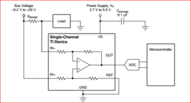
I am looking for a DC current sense circuit which can measure 10-30A current with 0.5A accuracy. The shunt is 1mR. Which configuration of op-amp is suitable for this application? I want to use LM358.

Best regards
 

Hi,

It depends on a lot of things, like:
* Opamp power supply
* frequency range
* output voltage range
* and so on.

But let's just focus on the values you given:
* 0.5A accuracy
* 0.001 Ohm shunt
* LM358
It's rather basic to calculate the voltage across the shunt @ 0.5A... it's 0.5mV
And if you now look into the LM358 datasheet about expectable offset errors ... you soon will find out that the LM358 can not fulfill your requirement about accuracy.

Klaus
 

Thanks for reply

Op-amp power supply 5V
frequency range 50KHz
output voltage range 0-3.3V can be 0.2-3V

Please help to find suitable OPA device.

I am trying to build low side current sensor.

Regards
 

Thanks for reply.

The current waveform looks like this.

I want to measure the average value of the current.
 

Attachments

  • Current Waveform.jpg
    Current Waveform.jpg
    23.5 KB · Views: 117

Hi,

5V/ 0V single supply?

You want the"average", thus you need a low pass filter.
A low pass filter needs
* some time to settle
* and will have remaining ripple

How fast do you need the average value to settle ... and what error do you allow for this.
Also what remaining ripple do you allow?

Examples: settle to 1% error within 100ms. 1% remaining ripple.
--> results in a min. filter frequency of 3Hz (1% error --> about 4 tau, 4 tau = 100ms, 1 tau = 25ms, fc = 1/(2 × Pi x 25ms)
and a maximum frequency of about 500Hz, (1% ripple = 0.01, fc = fs x 0.01 = 500 Hz)
so I'd go with about 40Hz first order.(sqrt(3Hz x 500Hz))
(For the given example, rule of thumb)

I use the selection tools of distributors to find suitable devices. There I automatically get availability information and price.

Klaus
 

Are you sampling the shunt with an ADC, hence can use data to average, or
do you need averaging to be done in external HW ?

If onboard ADC or external what is the part number of ADC or processor you are using ?

Do you need average on a cycle to cycle basis or over many cycles ? Details needed.

Regards, Dana.
 

    adnan012

    Points: 2
    Helpful Answer Positive Rating
Hi,

is your current unidirectional or bidirectional (e.g. charge and discharge of a battery)?

Are you performing a high-side or a low-side current measurement?

What's your "system" voltage, e.g. 48 V battery application? This will influence your choice with respect to the common-mode input voltage your opamp can widthstand.

BR
 

If this is a "get it done" project then you'd be miles ahead using something like a LEM or Allegro current sense "IC" (somewhat similar form factor, all trimmed up for accuracy). Secondary questions include dynamic response (like, per-pulse short circuit vs slow battery draw monitoring).

If it's a "learn by doing" project then probably wading through error analysis / budget and per-candidate datasheet detail is the lesson plan.
 

Consider putting your sense resistor in the emitter leg of a transistor operated in common-base mode. Voltage is sufficient to affect B-to-E relationship, thus turning on the transistor to varying degrees. You can take a reading at the collector. (Feed it to an RC integrator to create an average.) By adjusting values it should be possible to obtain linear performance more or less.
Applying 100 gain yields readings from 0 to 3V.

measure 0 to 30A across 1m resis NPN common-base mode 5v.png
 

    adnan012

    Points: 2
    Helpful Answer Positive Rating
You can get signal but when basic scatter on the transistor Vbe exceeds full scale input you won't be seeing accuracy or consistency.

If low sense resistance is a gotta-have then you want a magnetic sense scheme (Hall, GMR). A fair bit of variation in speed, accuracy, form factor for you to explore.
 

You have a .5 A accuracy on 30A range, so a 6 bit ADC is all thats needed. To be good
to 1/2 LSB then use 7 bit ADC. Given the processor has a 12 bit ADC, all its errors results in
~ 10 bits , and its onboard Vref measured during production test and stored in the part
the LM358 will be overkill, except for its offset, 2 - 3 mV which corresponds to 2- 3 A error.

You could use a mux, measure the offset with ADC, and then the shunt, and correct
for error. But the ADC cannot handle measurement of a - Voffset. So just use a better
low offset OpAmp with - rail CM range. Of offset the input V to the ADC with a R
divider to Vref (rather than ground). If you go this way I have a calculator to generate
the need divider.

1672711195648.png


I would just G up the shunt V with better OpAmp, use 1% R's on it to set G, and be done with it.

Use G = ~ 1.2 Vref / 30 mV (30A thru 1 mOhm shunt) =~ 40.

Lastly given you are at 50 Khz, a FS step in current has to be < 20 uS, total slew + ADC
conversion time. The LM358 (example) will slew the 1.2V gained up step in ~ 2 uS, so
you are good to go there. Note ADC good for ~ 1 uS conversion time. So you have
plenty of time to get/convert/DMA the sample out to memory.

Note on layout, the shunt current should meet all the other processor and analog
current as close as possible to the source. So you do not generate more error, also
in light of the fact the LM358 (if you stay with that) has poor - rail PSRR.


Regards, Dana.
 
Last edited:

Thanks for reply.

I am using stm32F0 (12bit ADC) series MCU. The the supply voltage of LM358 is 5V. I am measuring lows side current.

How to calculate the error introduced by input offset voltage and what it offset balancing or cancellation? Suppose if the OPA has 2mV to 7mV input offset voltage how to use this information in calculation.

What abut MCP6022 OPA, is it a good choice?

Best Regards
 

Hi,

How to calculate the error introduced by input offset voltage and what it offset balancing or cancellation? Suppose if the OPA has 2mV to 7mV input offset voltage how to use this information in calculation.
With the amplifier circuit ... the input of the amplifier is the shunt voltage.... since it is a 1mOhms shunt it has a ratio of 1000A/V or 1A/mV.
So if the amplifier (or anything else in the circuit) causes an error of 1mV at the amplifier input it will result in a 1A (output) error.
(It basically follows Ohm's law of the shunt)

Now
* opamp offset voltage
* opamp offset voltage drift
* noise
are Opamp errors referred to it's input.
So 1mV offset voltage results in 1A output (accuracy) error
So 1mV offset voltage drift and noise results in 1A output (precision) error

With simple offset correction you are able to improve in accuracy, but not in precision errors.


Klaus
 

As you can see the Voffset gets gained up by the 1 + 39k/1k = G = 40. So its
an error that can be +/- .5A, which in turn gets added to G error (tolerance
of G settings R's) and any other errors.

1672742186197.png


In order to calibrate out Voffset error you would measure the output of OpAmp with input grounded,
then subtract that reading when shunt is applied to input. Note to handle a - Voffset the OpAmp has
to have a negative supply. or use a R divider to V+ at input to OpAmp to allow for - inputs,
as previously mentioned.

There are arm processors out there that can handle, w/o a - supply, measuring - outputs of shunts,
and can do the analog muxing needed. And have the G onchip as well.

This design is, with a 1 mohm shunt, produces 1 mV per amp thru shunt. So 7 mV =
7 Amps.

You can get better OpAmps, for Voffset, which is the easiest solution.


Since you are averaging you are improving precision.

If you want to find the mean of a stationary statistical process, averaging will provide a consistent estimator, i.e. one for which the uncertainty decreases as the number of samples increases. So you get better precision but not necessarily better accuracy.

General OpAmp errors :


Regards, Dana,
 
Last edited:

    adnan012

    Points: 2
    Helpful Answer Positive Rating
Hi,
I want to know how INA181 type current sense amplifier manage to work with high common mode voltage with low VCC level?

Best Regards
 

Attachments

  • 1678930107875.png
    1678930107875.png
    28.9 KB · Views: 106

Status
Not open for further replies.

Similar threads

Part and Inventory Search

Welcome to EDABoard.com

Sponsor

Back
Top