Continue to Site

Welcome to EDAboard.com

Welcome to our site! EDAboard.com is an international Electronics Discussion Forum focused on EDA software, circuits, schematics, books, theory, papers, asic, pld, 8051, DSP, Network, RF, Analog Design, PCB, Service Manuals... and a whole lot more! To participate you need to register. Registration is free. Click here to register now.

Induction Heater Coil Design

Status
Not open for further replies.

sabu31

Advanced Member level 1
Joined
Jan 28, 2011
Messages
441
Helped
12
Reputation
24
Reaction score
13
Trophy points
1,298
Activity points
5,103
Hi all,

I wanted to know about the resonant inductor design with DC input from low voltage (say 24V to 36V) for 1kW induction heating system. Since the current is higher as compared to a high voltage system, will the inductance required and hence number of turns reduce as compared to a high voltage induction system.

Thanks
 

Not necessarily.
The induction coil needs to match power into the "load" impedance coupled to it.

Its the nature of the heating load that determines optimum frequency of operation and tuned tank impedance.
If the tuned tank Q is too low, it won't couple power adequately, if the tank Q is too high, you will burn up your tank from excess circulating current.

It all needs to be designed around the shape, size, and material you intend to heat. Unless you can copy an existing design, a lot of testing and development will be required.

Its then up to you to figure out how to excite that optimally designed tuned tank from your low voltage driver.
 

Do we need to use transformer to step up to higher voltage which will then connect to induction coil ?
 

But how do you control power in this circuit. Also can it be scaled up to 50A or more
 

Power of resonant induction heater circuits can be reduced to a certain extent while keeping ZVS by increasing the frequency and completely by using phase shifted bridge topology. Not specific to intended low voltage operation.
 

Do we need to use transformer to step up to higher voltage which will then connect to induction coil ?
I think a comparable situation might be my soldering gun. It plugs into 120 VAC, and contains a step-down transformer. The secondary is a few turns of 8 gauge wire. It carries a great many Amperes, enough to make a thick copper bend red hot. Yet I measure less than 1V in the secondary. Small voltage, many Amps.
 

    sabu31

    Points: 2
    Helpful Answer Positive Rating
Dear All,

I need to design an induction heater coil (pancake shape) for a system that should work with 24-48V input and around 1kW power.

Now commercially available coil for use in 1kw domestic induction cooktops is typically 95uH and 0.5mOhm(AC Resistance) at around 30kHz. When a vessel is placed, it changes to around 65uH and 2Ohms.

In Low voltage systems, copper tubes is seen to be used with typically around 1-2uH.

My Doubt is.

a) How do we decide what should be the required value of inductance (hence the number of turns/inter-turn distance)? Assume the frequency is 100kHz.

b) What is causing the decrease n inductance when the vessel is placed on top.?

c) Any software/ reference for the design of coils for low voltage high current system
 

I think a comparable situation might be my soldering gun. It plugs into 120 VAC, and contains a step-down transformer. The secondary is a few turns of 8 gauge wire. It carries a great many Amperes, enough to make a thick copper bend red hot. Yet I measure less than 1V in the secondary. Small voltage, many Amps.
Hi Brad ,

I am revisitng this thread. Is there any formula correlating the current , power and number of turns for a pancake coil .
 

Besides previous helpful replies...
I think the power parameter comes from power absorbed into the skillet (pot, pan). The aim is to keep the skillet close as possible to the wire, so that the ferrous metal attracts magnetic flux. This should ensure close coupling, so the induced eddy currents are maximum Amperes.
The wire can be bare as long as you prevent short-circuits to the skillet.

Make as many turns as needed so exposure is as large as the bottom of the skillet. Select wire gauge sufficiently thick to have little electrical resistance.

Don't know whether turns should be very close together or a certain distant apart.

Expect to make your first attempt a lesser-power version. Experiment with frequencies. Watch to see if a certain frequency results in maximum absorption of Watts into the skillet. How quickly can it boil 1/4 cup of water? Things like that.
 

    sabu31

    Points: 2
    Helpful Answer Positive Rating
You could control power with voltage, and the match (vs
metal loading) by frequency (looking for some peak or null
in a measurable quantity such as P-P current, at a fixed
voltage). You may need a series of knob-tweaks to home
in on it? I reckon an industrial system would probably
have either a fixed metal load, so no need to tweak, or a
"goal-seeking" controller that tunes match by either
tank C or frequency?

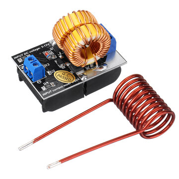
That linked module's coil looks pretty petite, and is not the
kind of configuration I've seen where the magnetic field
suspends the work in air, and cutting power drops the melt
out to whatever's below. That has a flared diameter, to use
the field divergence to levitate.
 

Status
Not open for further replies.

Similar threads

Part and Inventory Search

Welcome to EDABoard.com

Sponsor

Back
Top