Continue to Site

Welcome to EDAboard.com

Welcome to our site! EDAboard.com is an international Electronics Discussion Forum focused on EDA software, circuits, schematics, books, theory, papers, asic, pld, 8051, DSP, Network, RF, Analog Design, PCB, Service Manuals... and a whole lot more! To participate you need to register. Registration is free. Click here to register now.

Low transmit power on Collins KWM-2A

Status
Not open for further replies.

neazoi

Advanced Member level 6
Joined
Jan 5, 2008
Messages
4,122
Helped
13
Reputation
26
Reaction score
15
Trophy points
1,318
Location
Greece
Activity points
36,951
Hi, I have a low transmit power on all bands, apart from 40m, on a Collins KWM-2A transceiver with a PM-2 PSU.
I have done alignment of the RF circuits but it did not help the problem.
I have checked the voltages of the PSU. 275v is 265v, bias is ok, heaters are ok, unloaded (RX mode) HV is around 900v. Unfortunately I am unable to measure loaded (TX) HV.

I measured the voltages in the final tubes grids (pin 5, at C127) both on TUNE and on LOCK.
The second column is for TUNE and the third for LOCK

80m 145pvv 100vpp
40m 150vpp 100vpp
20m 145vpp 100vpp

On LOCK I get lower RF grid voltages than on TUNE. Maybe this is normal (loading of the driver plate) maybe not.

In the possibility that the PM-2 may be the problem and not be able to supply the HV current needed under load (so anode voltage drop), I investigated this PSU issue a bit. My PM-2 seems modified. I do not know if this was a modification that Collins did, but it is not the same as the schematics.
What I know for sure is that someone has been in there cause it was recapped on 1997 (there is a note in it)

Under load (PTT) I am unable to measure the anode voltage of the finals (not a suitable meter), so I do not know if the PM-2 is loaded.

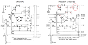
Here is the original schematic of the PM-2 and here are the modifications in my PM-2.
As you can see, an extra RC filtering state has been added in the HV, the capacity of the first filtering stage has been reduced to more than half, and an extra resistor was added prior to the diodes.

Note, I mentioned in a previous email that I did a swap on the 20R and 40R resistors, so that to bring the voltages close to 275V (265v now).

Maybe I should undo the modifications that the previous owner had (possibly) done and build the PSU as the manual states?

I fear that this 200R may limit the current to the finals and so, drop the voltage.
Although on 20m, where I get only 45-50W, the plate current reads 230mA.

What do you think?

By the way, why are these resistors are used between the transformer and the diode rectifiers?
Is it safe to remove them? In the HV line there is no such resistor in the original schematic.
 

Attachments

  • Capture.PNG
    Capture.PNG
    390.3 KB · Views: 156
  • KWM2A schem.PNG
    KWM2A schem.PNG
    5.4 MB · Views: 169
  • IMG_20220831_025356.jpg
    IMG_20220831_025356.jpg
    521.7 KB · Views: 137
  • IMG_20220831_025420.jpg
    IMG_20220831_025420.jpg
    570.8 KB · Views: 140

Nice radio in its day.
The 20 Ohm resistor in series with the diodes is to limit the inrush current in the voltage doubler. The original circuit has half the total capacitance of the modified circuit, before the red modifications. The modified circuit with the two 100uF smoothing capacitors should be better; less ripple and a more stable output voltage under load.
The 200 Ohm resistor at the output will reduce the 800V by about 40V at full current. I suspect it was added to reduce ripple caused by reducing the value of HT smoothing capacitors. KWM2 was supposed to have good audio
from what I remember, sagging HT will not help the intermodulation products one bit.
I would use the right hand power supply circuit you show with new electrolytic capacitors. It should be good to last for another good few years.
 

    neazoi

    Points: 2
    Helpful Answer Positive Rating
Nice radio in its day.
The 20 Ohm resistor in series with the diodes is to limit the inrush current in the voltage doubler. The original circuit has half the total capacitance of the modified circuit, before the red modifications. The modified circuit with the two 100uF smoothing capacitors should be better; less ripple and a more stable output voltage under load.
The 200 Ohm resistor at the output will reduce the 800V by about 40V at full current. I suspect it was added to reduce ripple caused by reducing the value of HT smoothing capacitors. KWM2 was supposed to have good audio
from what I remember, sagging HT will not help the intermodulation products one bit.
I would use the right hand power supply circuit you show with new electrolytic capacitors. It should be good to last for another good few years.
From the time I posted it I found out that there are two versions of the HV schematic. The first generation had resistors, but the newer second did not. This was to boost a bit the power and to compensate for the mil input voltage variations. Collins suggested to convert to the 1st schematic without the resistors but with bigger caps and all the later models all came like this as a standard.

Problem is that the radio seems to have close to full power only on 40m. On 80m for example it is only 25w.

I did a full alignment of the RF circuits as the manual describes. Not just the field alignment but the full alignment, the slugs and the capacitors.
I did it at least twice for the slugs and at least 3 times for the capacitors, just to make sure everything is peaked.

I tried also to turn a bit the loading trimmers, to see if there is any difference. The loading trimmers did not make a noticeable difference (weird...???) so I put them back to their original positions.

I also tried to turn a bit the neutralization and feedback trimmers of the driver and PA and they did not make a noticeable difference (weird...???) so I put them back to their original positions.

I have tested the PSU voltages after the Collins modification I did to it, and they seem ok. I am unable to measure the HV (800v) though, I am waiting for a new multimeter to arrive here so as to do so (to see if there is any loading that causes voltage drop at some bands).

The weird thing is that at 40m I get 80W at 230mA plate current and 100W at 250mA plate current.
On 20m I get 50W at 230mA plate current and 100W at 300mA plate current.
On 80m I get 25W at 230mA plate current and 50W at 300mA plate current.

Collins suggests only 230mA of current though.

So the radio seems capable of output some serious power on one band, although for full power it needs a but more mA (why???).
On the other bands power is reduced and I need to set the current too high.

The only thing that I can think of, is alignment of the RF circuits, which i have already performed.
I am starting to run out of ideas...
 

The only time I have had a problem anything like that was may years ago with a FT401. I can't remember the exact symptoms, but it was low O/P or would not tune up correctly on one or more bands. that turned out to be a faulty anode choke, I can't remember if it was on the driver or on the PA.
 

    neazoi

    Points: 2
    Helpful Answer Positive Rating
The only time I have had a problem anything like that was may years ago with a FT401. I can't remember the exact symptoms, but it was low O/P or would not tune up correctly on one or more bands. that turned out to be a faulty anode choke, I can't remember if it was on the driver or on the PA.
Was the choke shorted at some point? Blackened or other visual defects? Was it present significant resistance?What was it's fault and how did you find it?
 

I can't remember exactly what it was, but I think it was a shorted turn.
 

I managed to get 100W on 80m, only on the next conditions:

AC mains voltage 243v (the mains voltage currently here. Anode current set at 350mA
If I use my backing transformer, then
At 228v out of the transformer, I get 45W max at 300mA, which is the max current that can be set by the mic gain.

As far as I know, the nominal input mains voltage that the KWM2A expects is 230v and with the backing transformer I bring it to 2v less. The filaments are kept within voltage limits then.

Also, the current at which I get full power is much larger than it should be (230mA).

What does this tell you?
 

You mean the anode choke, or the choke that is connected from the antenna jack to the ground? That one is usually 2.5mH (millihenries).
Which of the 2 chokes you mean?

My protection choke, which is connected between the antenna terminals and directly in parallel to the loading trimmers, measures 6mH instead of 2.5mH!
 
Last edited:

The problem I had was with the anode choke. It looked fine, but had a short. I found it by a process of elimination, the drive and all DC voltages were OK. The Pi network could be tuned for maximum output, so the components there I guessed were OK, then there is not much else in the circuit apart from the valves, and the problem remined when I swapped them for a spare set.
Not knowing the history of this particular radio, my guess would be that the output tubes are not as good as they should be. From what I remember of transmitters using the 6146 at the output they can be rather particular about the manufacturer. I expect it is getting hard to find a 'genuine' 6146 any more and that those that are available are made in China or Russia and don't work quite as well in that circuit.
Mine uses 6146W made GE. I do not have a tester to test them, but they give full output on 40m. However, to get full output I have to set the plate current to 250mA and not 230mA as the manual states.
On the other bands, eg on 80m, I have to set the current to 300-350mA to produce full output.
same for 20m.
On higher bands, I cannot get good output, and I cannot increase the current enough.

My finals cathode resistors (six 12 ohms connected in parallel), measure in parallel as 2.6 ohms, where they should be 2 ohms. I also see a blackening at the middle of their bodies, like these were previously overheated. The plate current is read by measuring the cathode current.

Do you believe this 0.6 ohms difference is enough to cause erroneous current readings or more than 100mA?
 

Status
Not open for further replies.

Part and Inventory Search

Welcome to EDABoard.com

Sponsor

Back
Top