Continue to Site

Welcome to EDAboard.com

Welcome to our site! EDAboard.com is an international Electronics Discussion Forum focused on EDA software, circuits, schematics, books, theory, papers, asic, pld, 8051, DSP, Network, RF, Analog Design, PCB, Service Manuals... and a whole lot more! To participate you need to register. Registration is free. Click here to register now.

Comparison of Low-Parts Current Limiters

Status
Not open for further replies.

theboom

Junior Member level 3
Joined
Jun 4, 2022
Messages
30
Helped
1
Reputation
2
Reaction score
0
Trophy points
6
Activity points
209
I'm seeking an adjustable, cool-running, very low-parts, continuous current limit, Vin about 4V at up to 4A continuous.

  • Which of these limiters will run cooler, all things being equal?
  • Will they all simply regulate the current, ie continuous limit? Or will they turn off current on overcurrent?
  • Which would have fewest parts in a real-world practical circuit?
  • Are they all temperature-compensated?
  • Which would have the smallest PCB footprint, ie can they be implemented with all-SMD parts?
  • How do costs compare, including external parts?

What alternate circuits are there?


LM338
It seems this regulator isn't available in SMD. Can this be done with other linear regulators? Or just the LM series?
1654388559299.png


TL431
I was told this will run cool, but doesn't do continuous current regulation -- it turns off on overcurrent. True?
1654388708624.png


MOSFET
I'm thinking that with prudent selection of the mosfet (a high-current device with low RDSon) it will run cool. No?
1654388865380.png


SMPS
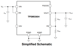
I'd be happy to find a switched regulator, if it provides adjustable continuous current limiting with very few external parts and comparable COG. The AP6230X series are cheap and plentiful at Digikey. They do "cycle-by-cycle valley current limit" -- i'm unclear if that's continuous current limiting i desire. Problem is, doesn't appear to be adjustable. Maybe some clever way to make the current limit adjustable?
1654390719692.png


Others?
--- Updated ---

Maybe some clever way to make the current limit adjustable?
For example, injecting current into the feedback pin?
 

Attachments

  • 1654389998967.png
    1654389998967.png
    33.2 KB · Views: 111
Last edited:

Which of these limiters will run cooler, all things being equal?
Unless it's a switching regulator limit, they all will dissipate the same power (Ilimit * Vin-Vout).
Will they all simply regulate the current, ie continuous limit? Or will they turn off current on overcurrent?
Unless it's an electronic-fuse type, it will just continuously limit the current.
Which would have fewest parts in a real-world practical circuit?
I believe you can do a parts count as well as I can. ;)
Are they all temperature-compensated?
Only those with a compensated reference, such as the LM317, and TL431 circuits.
Which would have the smallest PCB footprint, ie can they be implemented with all-SMD parts?
You would have to see if the parts are available in SMD packages.
How do costs compare, including external parts?
You can do that by looking at the supplier cost for the parts.
 
  • Like
Reactions: theboom

    theboom

    Points: 2
    Helpful Answer Positive Rating
I believe you can do a parts count as well as I can. ;)
But these schematics may be simplified compared to real-world practical circuits. You may be as ignorant of that as i am.
--- Updated ---

Unless it's a switching regulator limit, they all will dissipate the same power (Ilimit * Vin-Vout).
I've been told they won't dissipate the same heat. For example, it may depend on the thermal characteristics of a selected transistor. Do you have hands-on experience with any of these circuits?
 
Last edited:

Here's a simple current-limit circuit that requires only two transistors and two resistors.
The current limit value does increase about 0.3%/°C due to the change of Q1's base-emitter voltage with temperature.

1654448783538.png

--- Updated ---

But these schematics may be simplified compared to real-world practical circuits.
In general the number of parts seem close to what the actual circuit would have.
I've been told they won't dissipate the same heat. For example, it may depend on the thermal characteristics of a selected transistor.
Whoever told you that was wrong.
The heat dissipated is solely determined by the formula I showed.
The only thing the thermal characteristics will affect is how that heat will be dissipated to the ambient air.
 
Last edited:
  • Like
Reactions: theboom

    theboom

    Points: 2
    Helpful Answer Positive Rating
Here's a simple current-limit circuit that requires only two transistors and two resistors.
Great! Why might someone choose this design over any of the designs i posted above?

Will it handle 4A? That FET is marked -13.5A, –20 V. Will your circuit support positive V's?

Will the output V follow the input V?

When it's in limit-mode, is its behavior equivalent to a constant current device?

The current limit value does increase about 0.3%/°C due to the change of Q1's base-emitter voltage with temperature.
Is that the same as saying it's not temperature compensated?

How would that affect Vout in cold vs warm ambient temperature? I think "0.3%/°C" means current goes up as temperature goes up. And it looks like, in limit-mode, Vout goes down as current increases. Therefor, as temp goes up, Vout goes down, correct?

Could a TL431 help here?

The only thing the thermal characteristics will affect is how that heat will be dissipated to the ambient air.

"How"?
 
Last edited:

Why might someone choose this design over any of the designs i posted above?
Minimum number of parts.
Will it handle 4A?
Yes, if the power can be dissipated by the FET.
That FET is marked -13.5A, –20 V. Will your circuit support positive V's?
Yes.
The voltage across the P-MOSFET is positive source to drain (which is minus drain to source which is how the MOSFET voltage is specified).
Will the output V follow the input V?
If it's not in the current-limit mode, yes.
See below:
Note how the output voltage (yellow trace) closely follows the input voltage (red trace) until the current limit is reached.

1654488179463.png

s that the same as saying it's not temperature compensated?
Yes.
as temp goes up, Vout goes down, correct?
No.
As temperature goes up, the current-limit goes up.
Could a TL431 help here?
The current limit would be more stable, but the sense resistor would be about 4 time larger, giving a higher voltage drop when operating normally with no current limit.
How what?
Do you understand what thermal resistance is and how power is dissipated from a transistor?
Thermal resistance is the temperature rise due to the transistor power dissipation.
The thermal resistance from the transistor die to ambient air must be low enough so the transistor does not overheat (usually about 125°C).
For power above about a watt (depending upon the transistor) an added heat sink is usually required.
 
Last edited:
  • Like
Reactions: theboom

    theboom

    Points: 2
    Helpful Answer Positive Rating
Hi,

Some corrections:
they all will dissipate the same power (Ilimit * Vin-Vout).
correct formula: Ptot = I_limit * (V_in - V-out)
Mind the position of the brackets.

If it's not in the current-limit mode, yes.
even if the MOSFET is in the saturated mode there will be a voltage drop:
V_drop = I * (R_DS_ON + R1)
V_out = V_in - V_drop

No.
As temperature goes up, the current-limit goes up.
The bjt determines the thermal behaviour. V_BE has negative temperature coefficient.
Thus V_BE goes down with higher temperature.
This I_limit goes down with higher temperature.

Klaus
 

How what?
Do you understand what thermal resistance is and how power is dissipated from a transistor?
Thermal resistance is the temperature rise due to the transistor power dissipation.
The thermal resistance from the transistor die to ambient air must be low enough so the transistor does not overheat

Yep, i understand that.

You wrote:
The only thing the thermal characteristics will affect is how that heat will be dissipated to the ambient air.
Sorry for being pedantic. It seemed the word "how" might be misleading. "How" implies "manner", as in "the manner in which heat will be dissipated".

Wouldn't it be more accurate to say "how much heat will be dissipated"?

Question: Is it possible that different devices, with identical die-to-ambient thermal resistance, can withstand different degrees of heat?
 

Status
Not open for further replies.

Similar threads

Part and Inventory Search

Welcome to EDABoard.com

Sponsor

Back
Top