Continue to Site

Welcome to EDAboard.com

Welcome to our site! EDAboard.com is an international Electronics Discussion Forum focused on EDA software, circuits, schematics, books, theory, papers, asic, pld, 8051, DSP, Network, RF, Analog Design, PCB, Service Manuals... and a whole lot more! To participate you need to register. Registration is free. Click here to register now.

Element for producing half and one clock cycle delay in Cadence

Status
Not open for further replies.

Shishira

Junior Member level 2
Joined
Jun 8, 2018
Messages
20
Helped
0
Reputation
0
Reaction score
0
Trophy points
1
Location
Dresden, Germany
Activity points
228
Hi All,
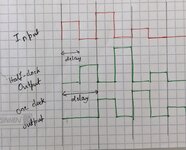
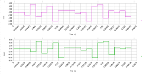
I want to introduce a delay of half and one clock period in an analog circuit. I need an element/circuit that can produce half-clock period in real circuit to be taped out. I cannot use a D flip flop as the output needed is an amplitude varying square signal. (atch 2). Looking forward to ideas..
 

Attachments

  • PXL_20220214_143536967.~2_exported_1644849424674.jpg
    PXL_20220214_143536967.~2_exported_1644849424674.jpg
    681.6 KB · Views: 144

Sample-and-hold is the all-purpose term for what you need.
A few methods:

* Switched capacitor circuit. (Hold sample for entire clock cycle.)

* Convert each pulse amplitude to a binary value (ADC), hold it briefly via latch, then send through a DAC.

* Store pulse amplitude in an inductor (rather, in the flux field of the inductor). Then discharge the energy to an output stage.

* Certain led's give off light briefly after current is shut off.

* A CdS photoresistor takes a brief time to respond to light intensity.
 

Hi,

A sample and hold will lose information. As long as it holds it can not react on input signal. And since it is 1.5 cycles you miss one edge.

The requirement of "1.5 cycles" is not useful at all. You need to be able to look into the future to know when 1.5 cycles are over. Esoecially when frequency is not constant.

If frequency is constant, then better state your requirement as a fixed delay time. Like "3.34 ms".

Delaying analog signal is difficult.
For delay times in the nanoseconds you may use a cable with the required length.
For delay in the milliseconds or higher I'd use: ADC --> digital FIFO --> DAC.

Klaus
Hi Klaus,
The problem is to get a delay of 0.5 and 1 cycle delay. Yes 1.5 cycles is not useful
 

Simulation portraying basic sample-and-hold. (Timing is performed in the manner which I grasp from the discussion.)

1) Sample incoming level during first half of cycle.

2) Send amplitude on capacitor to output during second half of cycle .

3) Reset capacitor by discharging it briefly.

Incoming voltage was changed during each idle gap.

Obtain 1.5 cycle delay by attaching a second sample-and-hold which samples the first level at an convenient moment.

sample-n-hold first pulse take amplitude later.png
 
Last edited:
Simulation portraying basic sample-and-hold. (Timing is performed in the manner which I grasp from the discussion.)

1) Sample incoming level during first half of cycle.

2) Send amplitude on capacitor to output during second half of cycle .

3) Reset capacitor by discharging it briefly.

Incoming voltage was changed during each idle gap.

Obtain 1.5 cycle delay by attaching a second sample-and-hold which samples the first level at an convenient moment.

View attachment 174435
Hey, that sounds promising thank you. But, attaching a second S&H should give a delay of 1 clock cycle isn't it?
 

Hi,

I´m a bit confused.

Can you please give an almost complete definition of the signal?
* Frequency (range)
* duty cycle (range)
* HIGH voltage range
* LOW voltage range
* are LOW always flat?
* are HIGH always flat?

Klaus
 

Hey, that sounds promising thank you. But, attaching a second S&H should give a delay of 1 clock cycle isn't it?

Yes and seeing your initial diagram I suppose that's the time length you want. Then extended to 1.5 cycles, it appears?

By putting two or more sample-and-holds in a row you create the bucket brigade concept. Capacitors pass along varying volt levels from one to the next. Hundreds of stages are in analog delay IC's (particularly audio) to generate phasing/ chorus/ echo effects. Example, MN3002 and SAD-1024.

To make a bucket brigade for your project requires some design effort, even to make two or three stages.
 

Hi,

I´m a bit confused.

Can you please give an almost complete definition of the signal?
* Frequency (range)
* duty cycle (range)
* HIGH voltage range
* LOW voltage range
* are LOW always flat?
* are HIGH always flat?

Klaus
The signal is ,
* fixed frequency say 32 MHz
* It's not a clock signal, it's a correction signal extracted for further operation. (It is sampled w.r.t to a clock signal of frequency 32 MHz)
* Vout range -500mV < Vh < 500 mV

This is a discrete signal and can take any value between 500mV < Vh < 500 mV. For a better understanding of my input signal I attach this waveform simulated from macro model.
 

Attachments

  • Half_cloclk_delay.png
    Half_cloclk_delay.png
    32 KB · Views: 100

Hi,

When I see the diagrams of post#11, I don´t think that it´s possible with 1 or two sampe-and-hold circuits.
The problem I see is how to get the correct timing when one can not rely on the signal edges.

Klaus
 

Yes and seeing your initial diagram I suppose that's the time length you want. Then extended to 1.5 cycles, it appears?

By putting two or more sample-and-holds in a row you create the bucket brigade concept. Capacitors pass along varying volt levels from one to the next. Hundreds of stages are in analog delay IC's (particularly audio) to generate phasing/ chorus/ echo effects. Example, MN3002 and SAD-1024.

To make a bucket brigade for your project requires some design effort, even to make two or three stages.
Okay, that sounds deep thanks. I actually need two output signals,
a) 0.5 (half ) cycle delay
b) 1 (one) cycle delay
--- Updated ---

Hi,

When I see the diagrams of post#11, I don´t think that it´s possible with 1 or two sampe-and-hold circuits.
The problem I see is how to get the correct timing when one can not rely on the signal edges.

Klaus
Hi,
Yes that's right, so there is no other way to delay the signal? I want to have an algebraic addition of these signals, say x[n] and x[n-1]. Fig is from Simulink model
 

Attachments

  • Sum_delayed_signals.jpeg
    Sum_delayed_signals.jpeg
    18.5 KB · Views: 120
Last edited:

Hi,

x[n] and x[n-1] often refer to the digital value of samples. On the digital side it´s rather simple.

Klaus
 

Hi,

x[n] and x[n-1] often refer to the digital value of samples. On the digital side it´s rather simple.

Klaus
Sorry for using the wrong notations, my question is restricted to the analog side. By n-1 , I just meant adding with the previous value (which is noting but delayed signal.)
 

Status
Not open for further replies.

Similar threads

Part and Inventory Search

Welcome to EDABoard.com

Sponsor

Back
Top